I think this is the right way to measure the noise on balanced outputs (one probe on each of the differential lines)...
Added the differential signals, the noise is low as approx 50mV for a approx 6Vpp useful audio signal. Please note that no filtering is in DAC analogue post processing signals.
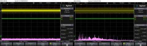
I took also some FFTs in this measurement configuration. The test signal are -1dB. I may say that it looks quite remarkable, with noises under 100µV for 5vpp on outputs...
Welcome your comments...
Added the differential signals, the noise is low as approx 50mV for a approx 6Vpp useful audio signal. Please note that no filtering is in DAC analogue post processing signals.
I took also some FFTs in this measurement configuration. The test signal are -1dB. I may say that it looks quite remarkable, with noises under 100µV for 5vpp on outputs...
Welcome your comments...
Attachments

Hey Coris,
The 4+4 implementation sounds impressive... that inspires me to try this one day in the future...
So far, I have been persuing the SEN route and have fully implemented it.
So far it sounds awesome much richer and true than the stock. My description is that when I hear truly high pitched sounds, I do not have to brace myself for it sounding harsh the top.
The midrange sounds more multidimensional and the bass more committed and precise rather than vague.
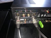
Installed a new set of balanced outputs so the original is still in place and operational to allow comparisons.
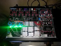
LEDs fully operational - Amber... batteries charging, Green - playing
LC filter circuit in case there is any distortion/noise from the battery power supply.
Getting used to it...
Future plans... have Coris' batter clock module ready to be installed - can't wait.
Now C' has totally intrigued me with the "4+4" configuration ?
cheers
The 4+4 implementation sounds impressive... that inspires me to try this one day in the future...
So far, I have been persuing the SEN route and have fully implemented it.
So far it sounds awesome much richer and true than the stock. My description is that when I hear truly high pitched sounds, I do not have to brace myself for it sounding harsh the top.
The midrange sounds more multidimensional and the bass more committed and precise rather than vague.
Installed a new set of balanced outputs so the original is still in place and operational to allow comparisons.
LEDs fully operational - Amber... batteries charging, Green - playing
LC filter circuit in case there is any distortion/noise from the battery power supply.
Getting used to it...
Future plans... have Coris' batter clock module ready to be installed - can't wait.
Now C' has totally intrigued me with the "4+4" configuration ?
cheers
Attachments
Last edited:
Well, well... you may have now a brilliant sound...😉😀
It looks like there is not so much more place for the clock board...
Else, yes you may experience 4+4... Do not forget to adjust then the I/V parameters...
It looks like there is not so much more place for the clock board...
Else, yes you may experience 4+4... Do not forget to adjust then the I/V parameters...
Last edited:
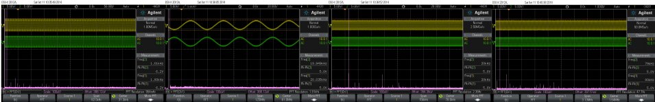
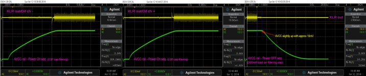
Some more detailed measurements on Power UP/DOWN sequences, and about HF noises on XLR outputs.
This time I was more accurate, and I have connected the probe via BNC connectors to the XLR output pins.
It seems that he modulated noise I have seen earlier (previously pictured), it may be caused by measurement issues. The modulation to be seen in the previous scope snapshots is about 50Hz, and it seems to be the usual AC main captured noise. The same modulation is gone in this measurement setup. The residual HF noise from the DAC (no filtering in signal path) it looks like continuous (no modulation), and it is located/concentrated in the 20-30Mhz area. There is no any special noise/signal in the low end of spectre (150Hz).
Attachments
Last edited:
Congratulations for your tweaks!
I don't have money for the moment but my stereo card may go back to you for moddings!
I don't have money for the moment but my stereo card may go back to you for moddings!
Congratulations for your tweaks!
I don't have money for the moment but my stereo card may go back to you for moddings!
I almost knew that...😀 You welcome any time...🙂
Last edited:
Well, going further to new improvements...😉
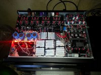
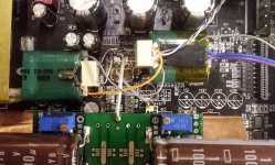
The second power rail for the analogue stage of the DAC chip (1,2v) have got its very large cap too...
A fully remarkable improvement for the soundscene dynamic, and its definition/resolution. Very precise location in space for every single sound element. No more confuse location for the low end spectre sounds, but only precision. Increasing in dynamics it just make the music be felt, experienced as in a life event, just in front of a band, or in the first row in a concert hall. Very impressive!
What is to be seen in the picture is only experimental. I have already in mind a dedicated PCB/layout for this analogue power stage of the ES9018 DAC. Very low noise regulators on board as these or even higher capacities too.
The only problem with this mod is that the power pins of the chip have to be disconnected from the original PCB (lift it up)... Well, for me there is not this a big problem...
Attachments
I think it's time to write a (brief) review about Coris mods after several weeks of burning components.
I've sent him my stereo card: it's simplier because certain mods require high soldering skill. In addition, you only have to solder coaxial cables and give 2 powers taken from the linear power module (in my case, OPPOMOD special edition):
- +/- 5v to charge the battery (only in standbye mode)
- +/- 15v to start & stop the clock's card (to avoid useless discharging)
All information needed & explainations are provided.
His solutions looked intelligent to me: only 2 clocks powered with a cell.
This was to test after SELLARZ clocks which were very good too.
I only have my ears & eyes to review and they are not perfect but here are what i can write about this.
Concerning video, you will see more details, picture is more sharpen. Verical & diagonal scrollings could be better but i think other material could interfere (king of projector, hdmi cable, power filtering, kind of LPM...). You may notice more noise in the background but i think this is normal because clocks simply reveals more details.
Concerning HDMI sound, there is a great improvement too. Better details in high frequencies, speakers transition effects well reproducted, extended bass...
For sure, i advice to split picture and sound:
- use HDMI1 for video
- use HDMI2 for sound
This was even the case with original OPPO105-EU...(better sound with HDMI2).
For this part, this tweak appears to be real and not very expensive. I'm not electronician and i was able to do it.
The most difference concerns stereo card reproduction of sound. There were lots of improvements in fact.
The quality of job and solders is awesome, here are modifications provided:
- Replaced rectifier diodes with Schottky type.
- Replaced main filtering caps (+/-15v)
- Replaced main filtering cap (5v)
- Replaced filtering caps (+/-12v)
- Rail -12v adjustable and equalized to +12v
- Replaced post regulators filtering caps for DAC power rails
- Replacing/adding more filtering caps to DAC AVCC.
- Improved AVCC regulator and Increasing AVCC to 3,5v
- Improved cooling for AVCC regulator
- Shielding DAC chip
- Modified/improved I/V stage
- Replacing decoupling caps I/V stage on balanced/unbalanced channels
- Replacing decoupling caps for final stage on balanced/unbalanced channels
- Improved AC coupling for balanced/unbalanced channels
- Installed battery powered clock board (216Mhz SAW Epson oscillator/divider – 0,2ps Phase Noise/ Abracon 20Mhz oscillator – 0,3ps Phase noise)
- Provided connection cable for clock board (to be connected to the player PSU +5v/+15v rails as instructed)
- Adapted trigger level for DAC clock input
- Adapted trigger level for clock transmitter (multichannel board)
and Coris has just discovered new ones not applied yet (no money for the moment). I cannot imagine that sound would be better!
The stereo sound is more realistic.
I don't have anything to reproach about my actual stereo card in fact.
Everything is perfect. Even FLAC 44.1khz/16bits is impressive!
Some recordings are really impressive!
I have discovered my speakers (modded klipsch RF63) require an absolute quiet and without parasite source to perfectly reproduce voices for examples.
I have to recommand this tweak to all OPPO 105 users. The original stereo sound of this blueray player was not at all perfect, lots of people noticed it but now, you don't have to buy an external DAC for sure!
Nota: this was even the case in original configuration: XLR (balanced) outputs are better than RCA (unbalanced).
An externally hosted image should be here but it was not working when we last tested it.
An externally hosted image should be here but it was not working when we last tested it.
Thanks tekko06 for your appreciations.
I would like to point out on something about eventual noises appreciations in video stage of the player. There are many factors which contribute to such noises on the picture. Part are sourced by the device/circuits itself, and part it come from the qualities of the material (digital signal) used for tests, or test procedures, or even the subjective visual appreciation of the user himself.
As usually there is not enough with only one modification to cure or solve an issue. or to increase dramatic the quality level for the device functionality.
An important source for noises in picture/video it consist in quite high thermal levels of the main circuits involved in video stage processing.
I have named it in a previous post, mainly as a joke, about an "ultimate" modification for this player. But beyond the joke there is a very real fact: cooling the environment the video involved devices is working, improve a lot the quality of the picture. There is a very simple modification, but very efficient for the quality of outputted signals.
The main processor low thermal working regime is essential for increasing the signal quality for both audio and video stages. There are two ways (both should be used) to establish a optimal thermal regime for this main device: a better heatsink (it will transfer the most of the thermal energy from the chip to the near environment), and a airflow to remove the heat from the enclosure. Only one component of this system is not enough for optimal result. Initially the Oppo designers thought right to use a fan in 95 model. Only the implementation of the idea was wrong...
In 105 model, the natural air flow is hardly realized inside the enclosure, and therefore inefficient to do a good enough ventilation. Also the heatsink for the processor is under dimensioned.
I strongly recommend this very simple, but efficient mod (see the previous post) to lower the thermal working regime for the inside components. Lowering the enclosure inside temperature as much as possible it bring to all other modifications a new level, and leads to quite high overall results.
Mainly I was focusing along the time on modifications to improve the sound of this device. Improving the image stage came as a consequence of the other implemented mods in my player. Part of these mods was presented here.
As for sound, I may conclude, after a long series of modifications in this area, thant the best ever results come from the improved power system for audio stage, a better clock system, a better/cleaner power for DAC chip, and improvements for the post DAC signal processing. But the biggest improvements for audio it come from the 4+4 DAC output configuration for stereo output. When this 4+4 configuration is directed to the differential/balanced outputs, the improvements are even higher.
Most of the users of this player never use the headphone output. Two pair of the DAC outputs channels are dedicated to the headphone out... Quite stupid, in my opinion.
One can decide which kind of output prefer (balanced or unbalanced) and dedicate all the DAC output channels to the chosen final output. In 4+4 configuration the DAC it give its highest quality level... Well, with some other improvements around it...
I`m working now to design and produce a dedicated PSU module for ES9018 power rails/system. After successful experiments with very large capacities on the DAC chip analogue power rails, I decided to do this mod in a real professional way.
A very small board with two lowest available noise regulators on it, and the decoupling caps (in Farads range) for AVCC and VDD L/R (fixed 1,2v and adjustable 3,3v) of the ES9018 chip, will be available soon as a single PSU module. With two such modules there is possible to completely power the ES9018 DAC chip, on all its power pins (analogue/digital), for the highest sound improvement level...
A complete and fully differential (balanced) stage, I/V & final buffers, with ultra low noise regulators on board, and optional choice for filtering, or straight signal path output, will be available too, quite soon...
Last edited:
Coris,
Regarding the 4+4 configuration, I'm surprised that this works. Normally, 2 channels are used for the headphone output, while the main output is muted. Alternatively the main outputs are active, while the headphone is Muted. I had always assumed that this was done digitally. So, are you saying that actually all 4 outputs are always playing music?
of course, if this works then you get improved signal-to-noise ratio.
Eric
Hi Eric
Your observation is right. The headphone out and the rest of the DAC channels have to be muted and activated alternatively (in opposition).
The mute of outputs is realized mainly by the relays placed for this purpose on all outputs. When the headphone is plugged in, the relays click and disconnect the rest of the outputs. My approach for the experiment was to connect all together the DAC output channels as 4L+4R configuration, and hear the result...
I have assumed that when the relays do the mute job, then the DAC channels it may rest active always, or there is no reason to apply mute function two times in the same places, on the channels itself and by using the relays on the same final outputs. My assumption was even stronger after the improvement I got as consequence of connecting the DAC channels together. The improvements are too important to be only the result of connecting together two pair of channels (2+2)...
Well, I verified this assertion more in details just today (after reading your post).
Simulating the headphone connection, and bypassing the output relays I was expecting to heave sound on balanced outputs, even though the headphone volume should be down to zero. As known the volume become active for headphones, when the headphone plug is inside its contact. My expectation was not confirmed... So, on balanced outputs there was active only the two pair of the DAC channels, the headphone ones.
In absence of a simulated headphone connected (but headphone volume at its max), while playback was running, I could notice an slightly increasing in dynamics. This make me to conclude that the DAC headphone designated channels, it may be active while the headphone plug is not inside the connector, but the headphone out is then of course muted by the relay, in opposition to the rest of the active outputs). To have a more clear conclusion about what is active and muted and when, I should actually disconnect/unsolder the balanced/unbalanced channels, and let only the headphone ones, while the simulated headphone should not be connected. I will do this test in the future, but right now is quite difficult, as over these channels connections are the ones coming from my very large decoupling capacities power supplies for ES9018. With the occasion of mountin in place the board I have designed for this PSU. I will do this test with the channels, too...
I could also notice a fade of the signal when connecting in/out the headphone, so the Soft Mute have been used in this case, supposedly a soft mute command send it through I2C lines, at the headphone plug in detect... But why they should mute with relays on outputs, and double this using some software mute functions available...?
I the mean time, until a final confirmation will be in place, I think I may correct my previous mentions to the 4+4 configuration, as a 2+2 configuration...
And why not, maybe somebody else will may do some tests about this subject, and come then with own comments, observations ...
Last edited:
Coris,
Thank you for clearing this up.
The soft mute function of course is very desirable and is presumably implemented on the digital side.
Eric
Thank you for clearing this up.
The soft mute function of course is very desirable and is presumably implemented on the digital side.
Eric
I think I may know now what really happen with the Oppo`s configuration of the DAC output channels in 105 model.
The DAC it is software configured alternatively (controlled by the headphone plug in place or not) to output only on two pairs of its available channels. This to make possible a separation of (independent) volume control for headphone as for the rest of the outputs. It is only unfortunate that Oppo chosen two pair of channels for headphone, instead for only one...
If so, it looks like there is not possible to have a 4+4 configuration for the DAC in 105/105D models. But this is very possible in 95 model...
If only by connecting together 2 pair of the ES9018`s channels, one can get so much improved dynamic and soundscene resolution/definition, I just wonder how it may really sound this DAC in a 4+4 configuration. I can`t wait to implement this in my 95 model...
I think I may precise that I have done simultaneously the mod of connecting together the DAC channels, and adding of very large decoupling caps on the chip AVCC/VDD L-R power rails. So the mentioned above improvements it may be the overall result of both these modifications.
Of course one should sequential modify, to right appreciate the results, but sometimes I really do not have enough patience, and I "shortcut" a little bit...
Last edited:
Hello.
I've been using OPPO 105 for a year. And have read that the sound of it could be improved.
What would you suggest me to do? What shoud be the main steps for improving of stereo?
I've been using OPPO 105 for a year. And have read that the sound of it could be improved.
What would you suggest me to do? What shoud be the main steps for improving of stereo?
I've to come back to the thread just to say Coris' job on 2 channels stereo card is absolutely fantastic and i have not the ultimate MOD!
Every song is a pleasure to listen with numerous details, excellent diaphony, noise...
Staudio just contact him by PM!
Every song is a pleasure to listen with numerous details, excellent diaphony, noise...
Staudio just contact him by PM!
If only by connecting together 2 pair of the ES9018`s channels, one can get so much improved dynamic and soundscene resolution/definition, I just wonder how it may really sound this DAC in a 4+4 configuration. I can`t wait to implement this in my 95 model...
Hi Coris
Have you noted this:
It is important to note that with this configuration in the '105 - to parallel up the two outputs (leaving the headphones untouched) from RCA and XLR, do not change the XLR Polarity for the XLR in the Settings Menu. If you do, it will change the polarity on only the output used for the old XLR circuit, but not the RCA section. Changing the XLR polarity means the output will be cancelled out and zero sound.
So I tell my clients not to touch the XLR Polarity in Settings.
Cheers, Joe
.
Hi Joe
Thanks for your advice and observation. It make sense also this detail.
I have actually not changed the XLR polarity in the modified device. I just ignored this setting as unimportant, unless one should have a very special configuration or reason to change this setting in the Menu.
I`m quite angry on Oppo design for 105 series, because two of the chip channels it left unused, if one do not need the headphones out...
It seems to me that the multichannel board/stage of 105/105 players it was ignored by the most of the modders out there... And it looks like are enough users who want to take advantage of these outputs.
While the stereo board it can deliver quite high quality sound (with the right modifications in place), especially when using the balanced outputs, the multichannel stage of the players is limited to an unbalanced design.
There is quite obvious that the balanced approach is superior in SQ, and some quality AV processors/amps it have such XLR inputs for multichannel configuration.
Well, what about to output balanced multichannel from an 105/105D device?
I think this it will be possible soon. I just finished the design of a fully differential (balanced) module, which include differential I/V stage (OPA1632) + differential buffers (OPA1632)+ an unbalanced buffer (different optional opamps). Filtering in between the stages is also on board and is optional for use. The board include two (adjustable) +/- regulators stages (TPS7A49/30) for I/V and buffers, as large decoupling capacities for the active circuits. Board dimensions 52/55 mm, 4 layers design.
This module it can completely replace the post DAC audio signal processing in Oppo players, or whatsoever DAC system, and is meant as an universal module for post DAC signal processing. I intend to send it soon to production...
I have used the opa1632 in my old mods to the Oppo 95. You only need one 1632 per channel and no buffers or filters after it. You simply use the resistor you want in the feedback to get the voltage out you want and bypass the resistor with a small cap....say 1000 pf....and a small resistor on output (50 ohm)....that is all you need. You use the positive out for single ended and use both outs for balanced. However, this does not sound as good as using 2SK170/LSK170 J-fet buffers on the output. The zero feedback buffers sound much more naturally holographic, pure and real (less electronic). However, this voltage out mode only gives you one volt rms per phase. You use a 5K resistor on the output of the DAC (paralleled) followed by a 1Meg resistor to ground along with a 330pf Wima for a simple single pole filter and on the output of the fets you use a great film cap with a WA Quantum dot on it and bypassed by a modified Wima cap (all caps with outer foil to output). I use Susumu tiny resistors that sound really great. No other parts needed except I use .15 modified Wimas right next to each fet pair (one jfet is the buffer and the other goes to negative supply as current source. I do use a 500ohm resistor between the gate of the lower jfet and the negative rail to make sure there is no oscillations. I use custom shunt regulated power for all four buffers but I am sure the LDO regs you suggest are good. I have modified several multichannel boards this way as well and some I have modded for balanced outs.
I updated a customers OPPO 95 to the new circuit and he is thrilled with the difference (he had the OPA 1632 circuit). As long as you do not need more that one volt RMS this simple circuit is really, really hard to beat. The fet circuit gives the output of the DAC an easy load (1M) and the output impedance is the fets output impedance (around 50 ohms)......pretty neat.
I updated a customers OPPO 95 to the new circuit and he is thrilled with the difference (he had the OPA 1632 circuit). As long as you do not need more that one volt RMS this simple circuit is really, really hard to beat. The fet circuit gives the output of the DAC an easy load (1M) and the output impedance is the fets output impedance (around 50 ohms)......pretty neat.
Thanks Ric for your intervention/suggestions. I may say that I tried to get the signal out just after an 1632 I/V (no buffer). It was a not happy ending result... Maybe I did it not just right, but I will try again.
I`m also sure that it may be many versions to right output the DAC signals. Keeping experimenting...
I`m also sure that it may be many versions to right output the DAC signals. Keeping experimenting...
- Home
- Source & Line
- Digital Source
- Oppo's BDP105 - discussions, upgrading, mods...