I updated a customers OPPO 95...
Hi Ric
Just wondering if, like Coris and myself, have gone over to SAWs for the Sabre DAC? Hope you are and it's also better value for you and the end user.
Cheers, Joe
.
I updated a customers OPPO 95 to the new circuit and he is thrilled with the difference (he had the OPA 1632 circuit). As long as you do not need more that one volt RMS this simple circuit is really, really hard to beat. The fet circuit gives the output of the DAC an easy load (1M) and the output impedance is the fets output impedance (around 50 ohms)......pretty neat.
The DAC itself isn't improved by 'unloading' the OP. In fact the more resistive
load you put on the DAC the more linear it gets till you end up with a dead
short, the classic virtual gnd, where it is most linear.
Unfortunately then you need some sort of I-V and that means opamps or
current steering circuit. Back to more complexity.
There's always some kind of trade off but deciding which to make is the fun
part! 🙂
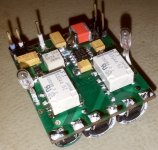
The final version of my AVCC/VddL/R PSU is now up and running...
It use a total capacity of 2,5F (60mOhm ESR) for AVCC, and 3F (80mOhm ESR) for VDD L/R. The regulators: AVCC - ADM7151 (adjustable), Vdd L/R - LDLN015 fixed 1,2v Input power: no more than 5v. Discharge circuits are protected by resettable 200mA fuses. Board dimensions: 35/30 mm
The module power lines are independent, with separate grounds. The grounds are to be connected together at the power ground point(s) of the DAC chip, using of course, the shortest possible connections.
Two such modules it can deliver the low noise power for the whole ES9018 chip.
Attachments
Last edited:
Hi Ric, haven't had an answer, but I assume yes - I think that's great, I have no agenda asking. Cheers, Joe
Unfortunately then you need some sort of I-V and that means opamps or
current steering circuit. Back to more complexity.
There's always some kind of trade off but deciding which to make is the fun
part! 🙂
Very true. Hope you are doing well Terry.
I have a question for you, with sigma-delta DACs like the Sabre used in the Oppo, what is the frequency of the PDM on the output. I ask because Mike Lenehan has finally found a non-ladder DAC that in his view is better (their own Ghistler/PDX Konverter [with a "K"] with 1704U) in the new PS Audio Direct-Stream DAC. I never thought that I would hear him say that. It outputs at 5.6xMHz and uses transformers. That is double-DSD or same as DSD128, is the Sabre same as DSD64? The PS DAC definitely uses s-d modulation.
Give a call sometime. I have a reason for asking the above.
Cheers, Joe
Hi Joe,
Thanks, I'm doing OK but it's a long tricky road back to 'health' and that new
version of health involves some very challenging eating procedures. But as
Nile Rogers says - "I'm still on the right side of the dirt" !!! 🙂
I'm away this weekend for R&R will call you next week.
PS audio is basically filtered raw DSD128.
Reminds me of these SACD upgrades that some blokes from VSE used to do
🙂
cheers
T
The final version of my AVCC/VddL/R PSU is now up and running...
It use a total capacity of 2,5F (60mOhm ESR) for AVCC, and 3F (80mOhm ESR) for VDD L/R. The regulators: AVCC - ADM7151 (adjustable), Vdd L/R - LDLN015 fixed 1,2v ...
Dear Coris,
I'm pretty convinced of the benefits of high capacity but would like to ask you 2 questions.
Do you place your caps before or after the regulators? By the book, the LDLN015 has a max output cap of 4.7 uf.
Don't you have any timing issues? I read that some dacs needs to have theyr differents voltages that appears in a certain sequence with certain delays. I imagine that loading 3F may take some time.
Thanks in advance and best regards.
Philippe
Hi Philippe,
I have placed the caps after the regulators. The caps role is more as decoupling caps for the DAC chip`s power rails. Well, a so huge capacity it can do the job as everything... But it looks like the best role is to simulate a battery for the powered device...
The actually role(s) of these very large capacities in this configuration, it can be discussed quite much. The fact is that it improve a lot the sound performances of the Sabre chip.
I was myself quite sceptic and enough prudent in the beginning to use such caps. I did it gradually, using bigger and bigger capacities (but small dimensions). I have observed that the quality of the sound it improve every time, as bigger the capacity was. This my observation was also confirmed by another member here, RayCtech. There are also some limitations in using large capacities, and one is just the longer needed time to get these caps charged. I found these values I use on my board as enough practical for the purpose.
I was also thinking that such capacities it may be a serious challenge for any regulator device, and of course I have read the datasheets of the regulators I used. In theory no any producer recommend using of Farad capacities at the regulators output. But what about to try it? it works well, no harm and the DAC power rails it benefit of a very well simulated battery power. It seems that the regulators role in such "design" is more as charging device for the huge capacities, than as a regulator device. Well, it may not be just necessary to use very low noise regulators in this configuration, thinking that the Farad cap it will kill any possible noise. Well, I`m not very convinced of such thinking way, so I prefer to use the lowest possible regulators for this task. Of course, paralleled with some good quality small capacities.
There is no any timing issue whatsoever. Well, there are some clicks and pops while the Sabre DAC it get the power increasingly in a slow way. But these noises it exist however while a fast power up sequence. That for Mute function and relays on the device line outputs... The problem is that the power up sequence when using so large capacities it exceed the delay time of the designed protection functions of the player. But I have establish my routine to start up the player first, then the amp, after a while...
In the beginning I could not know of course, how ES9018 it will behave at this slow power up sequence. I took some risks... The chip accept well such "power on sequence", as it accept the over-clocking "torture"...😀 Just a wonderful chip design!
At least this DAC chip do not need special power up sequences for analogue rails. As I could notice so far...
The loading of the 3F cap it take approx. 15sec. There is not only the charging time a possible issue for a regulator device, but the discharging too it may be more dangerous, as it keep a tension on its outputs, while the input is gone. Well, it seems that the designers of the regulators did a very good job, and the devices are quite well protected. At least these I use on my board... However, I do not want to play with it to switch it on and off without discharge first completely the Farad caps...
As a conclusion: everything it works just fine in this configuration, and the results are quite spectacular when powering ES9018 so.
Last edited:
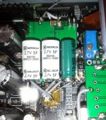
Implementing the Sabre PSU board...
So, the board in its place, connected to the ES9018 chip.
I used the existing/original AVCC regulator, and modified it to be adjustable for a 5v output. This it power my Sabre PSU.
I think I may precise and correct some informations in my previous post.
I have tested my PSU with a lab power supply, which it have large current capabilities. In this configuration my PSU it came up to the normal levels, in approx 15sec. When using the power configuration existing in the player, my board it need 35sec to finish the charging of the large capacity caps (for AVCC, while VDD it come up in 5sec.). This because the LM1763 used in original AVCC PSU it limit the charging currents in its particular way.
It looks like the large capacity caps I planted on my PSU board are better quality, than the caps I used in my previous experiments. The discharge time using the same type loads is longer (up to 2 min.). The PSU board is provided with a port for connection of an external load device/lamp to signalize the complete discharging of the caps.
However, the charging/discharging time is a marginal aspect for the functionality of the PSU board, when using these very large capacities.
The increasing in quality for the analogue power rails of the ES9018, using these very large capacities, is very obvious for the outputted sound quality...
Attachments
Last edited:
The increasing in quality for the analogue power rails of the ES9018, using these very large capacities, is very obvious for the outputted sound quality...
Hi Coris
In my view, as the PDM switches to full rail, then any noise or aberration on that power supply rail impinges on the D/A conversion and since we are talking about noise, then that noise will translate into audible jitter.
I also suspect that the switching itself is not noise free, as switching often creates back-EMF in real life, that pollutes the rail and hence is exposed when the switch is in the 'on' position. I believe that filtering as well as storing energy, or packed electrons if you like - becoming an electronic flywheel, is needed. That means that active solutions are limited and that passive solutions are the order of the day. I know what you are doing and I can confirm I am doing similarly. Can I point out that there are four 'core' power supply rails on ES9018 and the 1.2V need a full 1F IMO, as the joule capacitor is a lot lower because of the low voltage, and it is the joule factor that is most important.
Cheers, Joe
Hi Joe
Can you please extend "PDM"?
A switching system is noisy. This is a very real fact. The active power and filtering solutions are not only limited, but there are itself noisy too. This is also another very real fact.
Another fact/aspect in this approach is the energetic one. To output power and right dynamics a system/circuit need power to fully cover its own use and to put into the outputted signal. If is not enough power in the system, the altering of functionality become obvious. In today technology there is not any active power device which is capable to give instant clean power when needed. Some few very simple and passive devices, as a battery and a cap it can... A fully adjustable battery? Does not exist yet... But a simulation of a such power source it is available, is simple, clean and very efficient: a good regulator connected to a huge capacity device... Not about in datasheets about such use? So what? It is working? Then use it...
A few Farad cap it can deliver instant energy of around 10A. Does not exist a active device capable to such...
To really feel the very low frequencies reproduced by a audio system, there is needed lot of instant power. Just imagine how much power it use a drummer when hit his drums so to be heard and felt by a large enough auditorium. The same (instant) power is needed by an audio system to reproduce the same air vibrations/sounds... To have a audio signal capable to reproduce accurately the very low end spectre, one have to power accordingly that signal source...
Well, some considerations about the "core" of my concept and this PSU approach.
You pointed right about 1,2v core power and the cap for this rail. I had in mind to use a larger capacity for this rail, but I chosen at least for dimensions reasons this 3F. It should be however a much bigger capacity for 1,2v than for AVCC rail. I had also in my plans to experiment with a 6F one...
I have to say that the bass reproduction when using this PSU is just over expectations. I never believed that my audio system is capable to reproduce such natural, powerful and detailed low end spectre (for the same volume level). Definitely a way to go...
Last edited:
Oppo BDP 95 105 and 105D
I am wondering what the consensus is for upgrading the BDP 95, 105, and 105D. I do not care for headphone output, but I am interested in getting the best picture and sound and wonder which is the best player to mod to get the best picture and sound?
Is it possible to upgrade a 95 or 105 which would turn it into a Darbee Edition with elevated picture and sound which would match or exceed a 105D?
The upgrades I would like to see would have elevated audio and visual enhancements, better shielding in critical areas where it is needed (like perhaps the clock and or a/v or IC areas), damping on the chassis - which I could handle since I have dynamat extreme, and Femto Clock Upgrades.
What is the consensus here?
Thanks.
More questions
One thing I forgot to mention -
I don't care about digital volume control, since I would use the unit through an analogue preamp. And would it be better to disconnect the headphone output in hopes of getting better audio output through 2 channel balanced and unbalanced, and multi-channel output?
One thing I forgot to mention -
I don't care about digital volume control, since I would use the unit through an analogue preamp. And would it be better to disconnect the headphone output in hopes of getting better audio output through 2 channel balanced and unbalanced, and multi-channel output?
I am wondering what the consensus is for upgrading the BDP 95, 105, and 105D...
If video is also important, then I suppose the 105D.
When you say best sound, I assume stereo?
You can disable the entire multi-channel board if it is not needed.
Cheers, Joe
Thanks Joe. I guess multichannel would be important to keep enabled in case I want to listen to surround sound or if I want to sell the unit at a later ime. Would keeping multichannel sound enabled degrade two channel sound with or without mods?
Thanks Joe. I guess multichannel would be important to keep enabled in case I want to listen to surround sound or if I want to sell the unit at a later ime. Would keeping multichannel sound enabled degrade two channel sound with or without mods?
If you need the multi-channel, then don't disable it - from a purist point of view, if you only want to use stereo, then OK, but other than that I would not lose too much sleep about it.
Cheers, Joe
.
As one may notice from my previous post, for improving (in my way) the power system of the DAC chip, it involve a separation of the DAC power pins from the original power system. This mean a delicate operation: lifting up the involved chip pins.
In my previously published pictures one can observe the connections of the power pins of ES9018, are made using soldered solid (silver) wires.
I may say that in the last time I have developed a more professional technique which allow this (power mod) operation to be more easy done, with higher quality results, and less risks. I will publish a picture about, when the main component of this mod it will be produced, and the modification implemented.
Thanks much for your responses. Here is a different question - would there be a better current or a gen behind the current version of a Blu-Ray player to purchase and have the audio modified to bring it to a reference-level playback Blu-ray player for audio while giving an excellent picture?
Pioneer Elite comes to mind. Does anyone have any thoughts of the Pioneer design layout? Superior to Oppo? I always thought of Oppo Blu-Ray Players as a superior design and craftsmanship over any box-store purchase of Blu-Ray players that are out there, and would be a cut above some of the other high-end players - such as Denon, Pioneer, or Marantz, until I started looking into this thread. If I should look elsewhere for the answers to this, please let me know.
I am most interested in both two channel and multi-channel audio elevations, and if picture can be elevated even further, then I would consider that as well.
Thanks everyone for your time!!!
So Coris,
This power supply upgrade seems interesting.
Your design seems very sophisticated and interesting.
To implement a version of your power supply, I had already upgrades to 2700uf low esr caps.
I wonder if I upgraded these to the 5f and 3f values but installed an additional relay to short the caps to ground at turn off... triggered by the same circuit that mutes the outputs.
It does not have the visual led reference or the re settable triggers or the new voltage regulators, but I wonder if this would get some way to the quality of your design.
great work as usual.
- Home
- Source & Line
- Digital Source
- Oppo's BDP105 - discussions, upgrading, mods...