Actually the ESS DAC is a bit of the odd man out, sort of schitzophrenic, not able to decide whether it wants to be a voltage out DAC (Zout = 0) or a current out DAC (Zout = infinite).😉
The cleanest option, if you insist on buffering the output, would be the following.
Use an I/V opamp (discrete or chip as you fancy) like Coris showed. Use a feedback resistor that has the same value as the DAC Zout (around 780 ohms). That will give you current loading of the DAC and an output level the same as the open output level of the unloaded DAC. Also, (if you use a good opamp), no noise and distortion penalty!
It may not conform to current fashion, and you may subjectively prefer an other configuration, but for the cleanest sound there's nothing better. The best way to reap the benefits of Joe's clock and low jitter mods!
jan
which is exactly what I do on one of my ESS, but with 195Ω on a stereo out (781Ω || 781Ω || 781Ω || 781Ω = 195) buffering the output to provide no loading/low impedance does net you another ~10dB THD+N versus an ideal voltage output scenario, which is NOT just connecting a resistor to the output, that will not get near that, DNR is roughly the same though.
speaking of which, that means this 20Ω resistor is another 4x lower given this dac doesnt parallel the outputs.
on my other 2 ESS Irun common gate IV with high GM mosfets and set the gate to AVCC/2 a tiny touch shy (-115dB THD+N) of top flight opamp performance, but a bit more fun
in both cases I LP it, multiloop FB on the opamps, mosfet gate/out cap (parasitic ie. Ciss/Coss) for the common gate
Last edited:
BTW are the circuit diagrams of the Oppo in this area available in the open?
jan
No. Unfortunately not leaked...yet
I'm a lurker and a plodder - I'm so pleased to see open (and valued) discussion. It's how these threads move forward I believe.
Now it come some documentation from me...
Maybe I should precise before this "dispute" began here, that this setup with 20 ohm resistor it was an experimental one. This kind of setup it may not be functional of course, because some facts: necessary too much gain after I/V, which it increase the noise in the system, offset issues due to the same very high gain, and few other negative things.
Even though all those negative sides, I could not notice (perceptual) bead sound (FM radio like...), but very good quality one.
I think to present you here those results and "a vous" to analyze and comment.
There are scope plots for the ("worst case") 20 ohm (feedback) I/V resistor setup with x50 gain on final opamp, on the Stereo stage which were modified like this, and a "witness" one which is Front L/R stage very intact and with similar quality with the original stereo one.
Then the same measurements with an 750 ohm I/V resistor and 1,3 gain on final opamp (the same procedure, comparing with Front L/R stage).
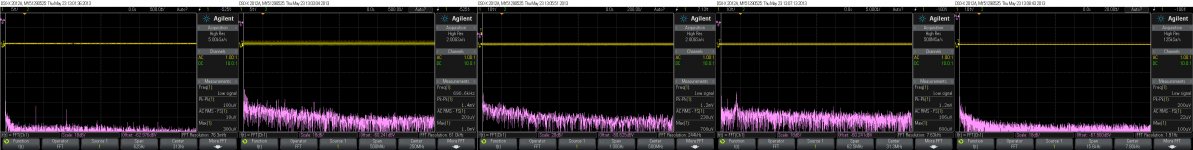
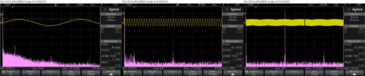
It were used for test 1Khz and 80Khz -3dB wav files (192/24) which were played back as normal on the player. The scope is set mainly to High Resolution Acquiring data, but it is used in some cases Normal too..
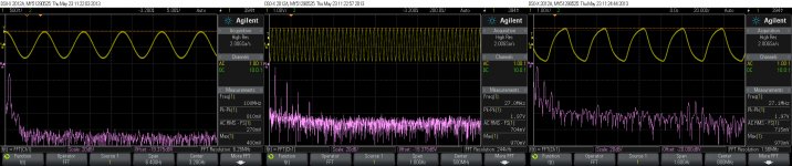
I use 108 Mhz clock for the DACs, divided to 27Mhz for the processor. This is an temporary clock setup, which is not very performant (specially the 27Mhz part one). There are first some plots of the clocks outputs, to make you an idea about how my scope it works with those clocks and the quite standard frequencies.
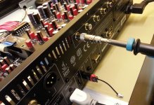
For the same reason I publish here some plots with the noise floor of my scope (shorted probe, 4mV scala (lowest not software amplified level), and so on. Also a picture of the measurements setup.
It will be quite many pictures, so many posts which it belong to this main one.
To see better the pictures, please download and zoom it.
Maybe I should precise before this "dispute" began here, that this setup with 20 ohm resistor it was an experimental one. This kind of setup it may not be functional of course, because some facts: necessary too much gain after I/V, which it increase the noise in the system, offset issues due to the same very high gain, and few other negative things.
Even though all those negative sides, I could not notice (perceptual) bead sound (FM radio like...), but very good quality one.
I think to present you here those results and "a vous" to analyze and comment.
There are scope plots for the ("worst case") 20 ohm (feedback) I/V resistor setup with x50 gain on final opamp, on the Stereo stage which were modified like this, and a "witness" one which is Front L/R stage very intact and with similar quality with the original stereo one.
Then the same measurements with an 750 ohm I/V resistor and 1,3 gain on final opamp (the same procedure, comparing with Front L/R stage).
It were used for test 1Khz and 80Khz -3dB wav files (192/24) which were played back as normal on the player. The scope is set mainly to High Resolution Acquiring data, but it is used in some cases Normal too..
I use 108 Mhz clock for the DACs, divided to 27Mhz for the processor. This is an temporary clock setup, which is not very performant (specially the 27Mhz part one). There are first some plots of the clocks outputs, to make you an idea about how my scope it works with those clocks and the quite standard frequencies.
For the same reason I publish here some plots with the noise floor of my scope (shorted probe, 4mV scala (lowest not software amplified level), and so on. Also a picture of the measurements setup.
It will be quite many pictures, so many posts which it belong to this main one.
To see better the pictures, please download and zoom it.
Attachments

Last edited:
Would replacing any of the regulators with a super-regulator like Dexa or Burson do any good you think? That, together with bypassing the output caps, was the mod I did to my Cambridge Dacmagic some years ago, with good results.
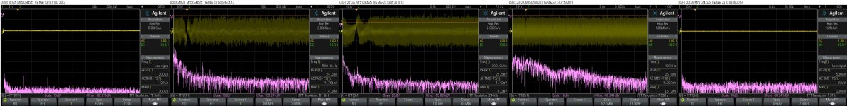
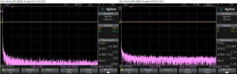
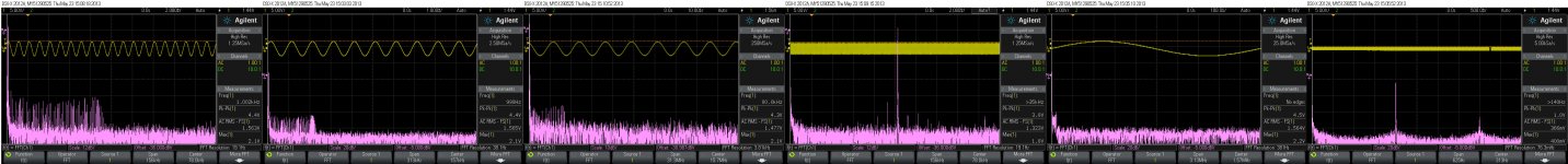
20 ohm I/V resistor and x50 gain on Stereo and Front L/R (High resolution Acquiring). Noise Floor of the outputs and with signals.
Attachments

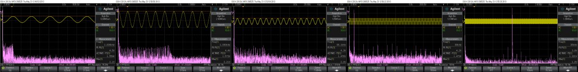
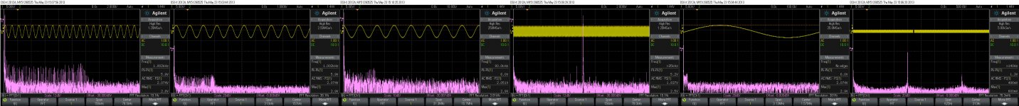
750 ohm I/V resistor and x1,3 gain on Stereo and Front L/R (High Resolution and Normal). Plots for Noise Floor of the outputs and with signals.
PS. My first comment is that are not big differences between an "bad" I/V setup and a "good/normal" one...
PS. My first comment is that are not big differences between an "bad" I/V setup and a "good/normal" one...
Attachments


Last edited:
Coris and Joe, you have been very informative as to the 'problems' with the OPPO 105.
About 6 mo ago, I was asked by OPPO to look at their audio output, and I have studied the schematics, and did listening tests on both the normal and the headphone outputs.
These designs are MADE TO A PRICE and while they are trying their best, OPPO also needs feedback as to how to make a better product. Your measurements have been very helpful to me to ascertain what is really effecting the sound of the OPPO from ideal. Keep up the good work, and don't worry about criticism. You are doing something useful.
..................................................
Keep up the good work, and don't worry about criticism. You are doing something useful.
Oppo should buy us a bear... 😀😀😀
Well, Coris, you could certainly start by suggesting to Oppo that they should match the resistors on the IV stage for the front left and right outputs (as you have discovered). They could start doing this in the next revision of the boards for no extra cost.
Joe I found somewhere (an ESS data sheet is a well-hidden secret) that the Rout is about 781 ohms
It's not hard to calculate and depends how many phases you parallel up. Yes, it is 3.05V unloaded (voltage mode), so the output is the ratio of the output Z divide by the I/V load seen at the end of it. Since it is 1:1 you can calculate the ratio from a single phase and multiply, so ((195+3.3)/3.3))*3.05 = 0.0333V - 33.3mV - that is of course with four phases paralleled = 195R approx.
The post-DAC circuit I use works with Moving Coil Cartridges down to 0.22mV with a gain of 1000 @ 1KHz and RIAA equalised to a gain of 100 approx @ 20KHz - these are gain structures @ 0.22mV and not 33mV. I use a gain of 60 aaprox to get up to 2V. Note that 3R3 x 2 is very similar to the source Z that is provided by Moving Coil cartridges and makes the input noise very low.
I remember it was impossible to get the datasheet and you had to jump through hoops and sign an NDA to get hold on it. We got it via a former audio designer with a very famous amplifier manufacturer called c-j. I suppose I won't get into trouble saying that now. We never spread copies except to our own Vacuum State Electronics Agents who were told to keep it confidential, and did.
Cheers, Joe
they should match the resistors on the IV stage for the front left and right outputs (as you have discovered). They could start doing this in the next revision of the boards for no extra cost.
Actually - I figured that out before Coris, as he had his '105 sitting dormant for a while and I didn't with mine. But I figure that Oppo won't change it since they believe it sounds better that way. Me? I ditch the opamps, want some? 😀
Cheers, Joe
These designs are MADE TO A PRICE
EXACTLY !!!
And thanks for the kind words.
Huh?
Ohhhhhh.... I get it, a BEER.
Sorry the fault... BEER it was... Not so much to do with a bear😉
Coris and Joe, you have been very informative as to the 'problems' with the OPPO 105.
About 6 mo ago, I was asked by OPPO to look at their audio output, and I have studied the schematics, and did listening tests on both the normal and the headphone outputs.
These designs are MADE TO A PRICE and while they are trying their best, OPPO also needs feedback as to how to make a better product. Your measurements have been very helpful to me to ascertain what is really effecting the sound of the OPPO from ideal. Keep up the good work, and don't worry about criticism. You are doing something useful.
Is quite obvious that the player is made to a price. The problem is at into the same price, or even more, at a lower production price, it is very possible to get out of this machine a much higher quality. Actually this it was all the time my point about the subject.
There is absolutely no reason at the new upcoming model should be more expensive, than 105 one. But is really possible to get more in quality by small design changes, with huge impact for improvements.
Keep up the good work, and don't worry about criticism.
Yes indeed, DON'T think for yourself! You might develop an independent opinion.
jan
I may say that I have nothing against critics/criticism when is done in a decent/positive manner.
Is one way to (arrogant) say: you are wrong, you have no clue about, you only do not know what you are doing, you are an amateur, sarcastic asking what is that good for, and so on...
And completely different way to critic when you may say: this it may be wrong, it may be a misunderstanding about, or I think it may be done so, BECAUSE... so and so, explain your point, come with arguments to demonstrate your critic position, use your competence in the field to make your point up...
A such positive manner to critic it leads to more discussions and it may bring out only benefit for all the parts involved...
- Home
- Source & Line
- Digital Source
- Oppo's BDP105 - discussions, upgrading, mods...