Here are few plots of some measurements.
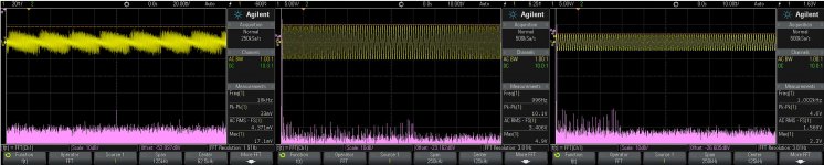
In the first picture, first plot show the noise on the 105 RCA-stereo outputs. This stage is modified as described in earlier posts here (no filters).
Second plot is the useful signal on the same output. The third plot is from the unmodified multichannels stage Front L/R output. This output is identical with stereo as signal quality.
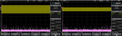
Second picture plots show the playback of a 80Khz signal from an wav generated file. On Stereo stage out, and Front L/R out.
The DACs are clocked with 108Mhz oscillator, which then divided to 27Mhz goes to the main processor. Higher amplitudes belong to the Stereo stage.
PS. Agree Joe 😀
In the first picture, first plot show the noise on the 105 RCA-stereo outputs. This stage is modified as described in earlier posts here (no filters).
Second plot is the useful signal on the same output. The third plot is from the unmodified multichannels stage Front L/R output. This output is identical with stereo as signal quality.
Second picture plots show the playback of a 80Khz signal from an wav generated file. On Stereo stage out, and Front L/R out.
The DACs are clocked with 108Mhz oscillator, which then divided to 27Mhz goes to the main processor. Higher amplitudes belong to the Stereo stage.
PS. Agree Joe 😀
Attachments
Last edited:
Coris,
you haven't specified which digital oscilloscope you are using, but you may be running at eight bit sampling (or somewhat more if your scope can do this). This is fine for identifying 2 MHz noise, or large 80 kHz noise on top of the signal, but will not be sufficient to do a modern analysis of the player. The player is outputting effectively 16 - 24 bit signals, which are then filtered to produce a smooth output (not to mention the upsampling aspect and technical details of the Sabre DAC). For a full analysis, you would want to bring your player to an audio precision analyzer. (Maybe you could find one at a local university).
you haven't specified which digital oscilloscope you are using, but you may be running at eight bit sampling (or somewhat more if your scope can do this). This is fine for identifying 2 MHz noise, or large 80 kHz noise on top of the signal, but will not be sufficient to do a modern analysis of the player. The player is outputting effectively 16 - 24 bit signals, which are then filtered to produce a smooth output (not to mention the upsampling aspect and technical details of the Sabre DAC). For a full analysis, you would want to bring your player to an audio precision analyzer. (Maybe you could find one at a local university).
Last edited:
The scope is DSOX 2012A, 8 bit vertical resolution. I'm not supposed to do a deep/full analysis, or an in depth review of the entire player stages. Such demanding and huge time consuming task I may let it to specialized entities... I have made only few empirical measurements, to compare and show to the sceptics what about few simple aspects between an modified stage and an unmodified one.
Some modifications in this machine bring quite important improvements (sound and picture). What is published here is a little part which it not show at last the opposite of this statement...
Some modifications in this machine bring quite important improvements (sound and picture). What is published here is a little part which it not show at last the opposite of this statement...
Coris,
The DIY forum is a place for exploration and adventure.
I don't think you have to prove anything. I have made my suggestions to you in the spirit of constructive engagement.
I'm very impressed with your willingness and ability to make bold changes to your electronics, and I enjoy reading your posts. I think you have made substantial contributions.
That is a very nice oscilloscope. It has a high-resolution mode which significantly cleans up the display of waveforms, and should also give you up to 12 bits, and therefore much lower background noise on your FFT calculations.
I do share the concerns expressed by others about increasing the high-frequency noise in the circuit when you remove the capacitors from the output sections. The dramatic reductions in the feedback resistor in your I-V stage may lead to reduced signal-to-noise ratio. That is not to say that these modifications are incorrect, only that they should be considered carefully. None of us can hear your system.
In any case, sometimes when evaluating everything by ear, one can go astray or can make "improvements" that are particular to your system or your tastes. In this situation, access to high-resolution test equipment can be revealing.
Warmly,
Eric
Coris/Eric
Whole heartedly agree, particularly >
"The DIY forum is a place for exploration and adventure.
I don't think you have to prove anything."
"I'm very impressed with your willingness and ability to make bold changes to your electronics, and I enjoy reading your posts. I think you have made substantial contributions."
Eric, thank you for articulating what (I’m about to be presumptuous) many people would be thinking.
In any case, sometimes when evaluating everything by ear, one can go astray
If I may but in? I have heard this said before and not against the point made.
But there is at times when listening for an improvement becomes more that just a subjective judgement. Yes, in that case, one may make a step that doesn't quite work as much as you'd like, but think it is doing something good, but since you have made five other steps that cumulatively has brought a large benefit, then that odd misfire in one-out-of-five or even one-out-of-ten "improvements" you made, the point is that you still end up way ahead and shouldn't be scared of a misstep or two along the way, because the end result is worth the odd stumble.
But one never hears about "objective" listening, and yet it does actually exist - even if not all the time.
For example, and having studio work under one's belt can prove this to be helpful, I can tell you that listening to a live feed of a Yamaha Grand Piano in the booth, live to speakers, that is some amazing sound that most home systems can only dream of. It isn't even close. Only very few systems can do this. Have you got one, then you don't even have to think about the obvious.
Another example, you get a recording where an acoustic guitar is double-tracked by the musician. When played back on your system you should hear that, yet often you may not. But let us assume that you do hear the double-tracking as you should, clearly distict two guitars. Then, and this happened for real, you made a certain change to that system, played it again AND it now dawns on you. The guitar no longer sounds double-tracked, but blow me down, it is TRIPLE-tracked. You just didn't know it until then - call the engineer/producer and ask "did you end up TRIPLE-tracking that acoustic guitar" and the answer comes back "yes".
Know this for sure, they would have heard that in the recording studio as they did it, as they "assembled" that track. It is a sobering fact that most people will never hear what they heard in the booth where it was put together.
So I often use this as a yard-stick when making "improvements" - can I hear things that I have not heard before on that system as a whole - because if the answer is "yes' - then the result DOES NOT LIE !!!
Cheers, Joe
Coris,
The DIY forum is a place for exploration and adventure.
I don't think you have to prove anything. I have made my suggestions to you in the spirit of constructive engagement.
I'm very impressed with your willingness and ability to make bold changes to your electronics, and I enjoy reading your posts. I think you have made substantial contributions.
That is a very nice oscilloscope. It has a high-resolution mode which significantly cleans up the display of waveforms, and should also give you up to 12 bits, and therefore much lower background noise on your FFT calculations.
I do share the concerns expressed by others about increasing the high-frequency noise in the circuit when you remove the capacitors from the output sections. The dramatic reductions in the feedback resistor in your I-V stage may lead to reduced signal-to-noise ratio. That is not to say that these modifications are incorrect, only that they should be considered carefully. None of us can hear your system.
In any case, sometimes when evaluating everything by ear, one can go astray or can make "improvements" that are particular to your system or your tastes. In this situation, access to high-resolution test equipment can be revealing.
Warmly,
Eric
Thanks for your considerations.
Reducing the I/V resistor it may indeed reduce some noises, but it need increasing of the following stage gain. So, the noise it may come back in the system... Even more, increasing the gain of the final stage it increase its offset on output (at last at the op amp type i use). This it may do it necessary to put back in place the AC coupling caps... It is a big dilemma here, so one may try to find the best compromise, if possible. I'm quite surprised by the fact that the DAC residual noise get much lower when that resistor goes very low in value. When in "voltage mode" that residual noise is just huge. The need of higher current on DAC outputs it seems to make it function better in one way... And this it may be in accordance with the remark of the father of this chip...
I`m not very sure about what caps you mention to be removed from the outputs. If you refer at the AC coupling caps, then those have nothing to do with the noise in the system, or the filtering function. They are there only to isolate/separate the DC levels from AC outputted signal. But, yes they have a filtering function too... It "filter" in a negative way the useful audio signal. You know, I just experimented and put it back a better quality (non polarised) AC coupling caps on that output, after I have modded this stereo stage. It were just horrible to hear the sounds with those caps there...
As one may notice from the plots published, the HF noises (with an arround 50Hz component), it have in this case 32mV. This level it is really possible to be lowered even more, without impact for audio signal. I did not yet this to have the worst case scenario, to judge the improvement. The amplitude of useful signal measured in the same place is in this case x366 higher. So the difference is huge. Never ever it will be possible to be heard that audio component of that noise out of the speakers (in normal listening conditions, or even in absence of the audio signal), but it is a benefit for the spectre quality of the rest of the outputted signal. Anyway this subject it may be discussed further on quite much...
When about my scope ( 😀 that is a quite funny story with that scope too, but I will not narrate that here... One may read about in Agilent forum), I know that it can be used the High Res mode. That it shows more clean everything. I have chosen deliberately Normal mode, to have again the worst case scenario, with the normal showed noises over the signal. In those worst conditions the difference between modded/unmodded stages in a part of the signal quality it still be there, at that level to make the sceptics to think about...
I may mention again that presenting here some things and experimenting results it not mean at all that I preach and push the people to make the same as I do. I think only that it may be out there some other people who may think and/or want to try something else, or new ways. What it is here it will serve as ideas, a kind of guide, or suggestions in the way they want (chose) to improve or find new things in this audio field. At last, yes is true that I do not need to prove anything, but I try to be as much objective as I can in this (freely) assumed task.
Last edited:
..................................................
So I often use this as a yard-stick when making "improvements" - can I hear things that I have not heard before on that system as a whole - because if the answer is "yes' - then the result DOES NOT LIE !!!
Cheers, Joe
Fully agree. Yes this is the clue with improvements in a system...
He is a Troll.
Maybe, maybe not. But I recognize the feeling, seeing people who have absolutely no clue what they talk about, messing up a perfectly good piece of eqiupment and wax lyrically about the 'improvement'.
jan
...messing up a perfectly good piece of equipment and wax lyrically about the 'improvement'.
Indeed, indeed.
There is an "A-B" factor that I have twice been part of exposing, via blind tests where two pieces of equipment were compared - and A and B were chanced at the toss of a coin. A piece of music was chosen, and played on one and then the other, the order being decided by the toss. So that sometimes A was actually B etc.
We found - even with exact level matching - that whatever got the "B" position (played second) would win the vote by typically 75% almost all of the time.
This was proved at ETF in 2006 - ask Guido Tent about it - and also at ASoN (Audiophile Society of NSW) in 2012. Both were conducted blind. The ETF one had many audio illuminaries present.
Just think how often a system has been played in a shop, then a change made, like a power cord or interconnect, or really just about anything, and watch how the customer marvels at the "improvement" heard.
That A-B factor (call it what you like), can you imagine how much equipment has been sold on the back of that trick, mostly unknowingly (some times not) in shops around the world for decades. Makes you uncomfortable even to think about it.
That is why since 2006 I have strictly avoided this method when demonstrating the difference between equipment, especially where I had a financial interest. I have a conscience - and glad that I do. I don't want to resort to a trick. A very powerful trick - try it on somebody sometime.
One must acclimatise to a piece of equipment in a known milieu, allow sufficient time, or get duped.
Cheers, Joe
PS: The above also applies to "shoot-out" - they mean NOTHING!
He has form.
Which, of course, is more important than content.
jan
Indeed, indeed.
There is an "A-B" factor that I have twice been part of exposing, via blind tests where two pieces of equipment were compared - and A and B were chanced at the toss of a coin. A piece of music was chosen, and played on one and then the other, the order being decided by the toss. So that sometimes A was actually B etc.
We found - even with exact level matching - that whatever got the "B" position (played second) would win the vote by typically 75% almost all of the time.
This was proved at ETF in 2006 - ask Guido Tent about it - and also at ASoN (Audiophile Society of NSW) in 2012. Both were conducted blind. The ETF one had many audio illuminaries present.
Just think how often a system has been played in a shop, then a change made, like a power cord or interconnect, or really just about anything, and watch how the customer marvels at the "improvement" heard.
That A-B factor (call it what you like), can you imagine how much equipment has been sold on the back of that trick, mostly unknowingly (some times not) in shops around the world for decades. Makes you uncomfortable even to think about it.
That is why since 2006 I have strictly avoided this method when demonstrating the difference between equipment, especially where I had a financial interest. I have a conscience - and glad that I do. I don't want to resort to a trick. A very powerful trick - try it on somebody sometime.
One must acclimatise to a piece of equipment in a known milieu, allow sufficient time, or get duped.
Cheers, Joe
PS: The above also applies to "shoot-out" - they mean NOTHING!
Joe, I agree with most of what you say, and the ETF shootout is of course great fun, it's not a controlled test by any stretch of the imagination, and nobody I know takes it seriously. OTOH, if the order in a well designed test, A or B, determines the score, that's a clear indication that there is no audible difference. Think about it.
But let me ask you: if someone makes a mod to a piece of equipment, increasing the audio noise 100 x, not just a bit, but two orders of magnitude, and he/she reports great improvements, are you just accepting that? No red lights flashing? No bells ringing? I can't imagine that.
Anyway, this is my last post in this thread. All the best,
jan
Joe: I know its hard to keep up with the meanings of all these hip internet terms, but its clear you have no idea what trolling is. if it was all about the reaction, you wouldnt be on my ignore list (meaning I wont see your reply). if you mean that I have a history of calling you on self promotion in the OPPO threads and similar handwaving behaviors as Coris, then yes I have form, but thats not trolling. i've stuck pretty consistently to my views, they just happen to be in disagreement with yours.
btw Coris, lower feedback resistance = MORE feedback, not less. I guess thats another explanation for the 'improvement' down the drain. thats opamps 101, its clear you arent clear on Ohms law either to think its the IV resistor ... its true its value impacts on the amount of voltage gain created in the feedback loop; i'll give you that. but its not a current feedback opamp and the ESS isnt really a true current source.
you dont think its logical that less gain = less noise? and less resistance = less johnson noise? seems pretty straight forward to me, but while noise itself is lower, SNR is much worse, as you have illustrated.
Last edited:

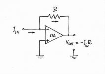
yes, but the resistor does not convert the current from the DAC in an inverting opamp IV convertor (your schematic example), it presents no load to the dac at all, it looks like a short to a virtual ground. a dac IV resistor is technically a resistor that sets a load point for a current output DAC and the voltage is created across the resistor to ground (or to whatever the load is, basically across the resistor), this loads the dac and drops some voltage (so there are losses)
is this correction constructive enough for you 🙄
is this correction constructive enough for you 🙄
Last edited:
lets forget for now that the current flows the other way, from ground, anyone who is considering mentioning that 😉 lets stick to old conventions for the moment, dont want to confuse matters
Coris,
…
I do share the concerns expressed by others about increasing the high-frequency noise in the circuit when you remove the capacitors from the output sections.
Coris,
Here I was talking about the original capacitors in the output filter stage on the op amps, not the output coupling capacitor.
I also still think that you would benefit by using the high-resolution mode at the frequencies below 100 kHz that we have been discussing. This would show a much clearer signal without scope artifacts, and also should show a significantly lower noise floor on the FFT analysis. This would reduce the concern of your critics, although the measurement would still not reveal the actual very low noise floor of the device. Try it.
Another strategy that you can pursue would be to study the noise on a -60 dB 1 kHz test tone. This way you wouldn't need so much dynamic range to capture the noise on your oscilloscope FFT. You would need an active probe, or a +60 dB amplifier.
I agree that it is fun and often very effective to listen to our modifications as we make them informally at home.
Eric
Example of
As an example of using high precision test equipment to study this player before and after modifications, we can look at this nice review from HD fever, at Test OPPO Muse modifiés par Espace-musical : une meilleure écoute analogique | Haute Définition sur HDfever
Of course, this is just part of a more elaborate series of tests. These tests can be found online, as you mentioned. You can see that the noise floor of the stock unit is already extremely low for this test signal.
Gamme Dynamique du OPPO 105EU de stock : sortie stéréo RCA
As an example of using high precision test equipment to study this player before and after modifications, we can look at this nice review from HD fever, at Test OPPO Muse modifiés par Espace-musical : une meilleure écoute analogique | Haute Définition sur HDfever
Of course, this is just part of a more elaborate series of tests. These tests can be found online, as you mentioned. You can see that the noise floor of the stock unit is already extremely low for this test signal.
An externally hosted image should be here but it was not working when we last tested it.
Gamme Dynamique du OPPO 105EU de stock : sortie stéréo RCA
An externally hosted image should be here but it was not working when we last tested it.
Gamme dynamique du OPPO BDP-105EU Muse : légèrement plus basse, et une nette diminution des pics, un signal plus homogène et naturel. La sortie frontale 7.1 est assez similaire
- Home
- Source & Line
- Digital Source
- Oppo's BDP105 - discussions, upgrading, mods...