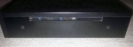
Look like it belongs in there 🙂
It looks very professional, like it belongs there.
Mark.
Then trying so...

It looks very professional, like it belongs there.
Mark.
I'm not a cable/wire guy but I would get Coris' take on the comparison. That patch-cord looks a bit thread-bare.Hi all, I wanted to share this with you all. I found a good cable to go from the headphone jack to RCA's. Found it on Amazon, here is the link.
Amazon.com: Hosa TRS-202 1/4 inch TRS to Dual RCA Insert Cable, 6.6 feet: Musical Instruments
I do agree Coris, out of the three outputs (Stock) the headphone sounds the best, though it does lack a little punch, but the increase in transparency and clarity especially in the upper frequencies is great.
Mark
It looks very professional, like it belongs there.
Mark.
I agree.
Update.
Update:
After reading many posts and material on Caps here and there I have decided to replace the Decoupling caps with the ELNA RFS Silmic IIs 470uf 16v (non-magnetic leads) tin coated copper.
I'm still looking for a film type bypass cap, one that will fit.
Moto.
Well I'm at a cross road, I have all the parts I need to replace the existing output caps. I have two brands, Panasonics OSCONS SECP 470uf 16v from DigiKey and ELNA RFS Silmic IIs 470uf 16v from Parts Connexion, and the bypass caps Wima 1.0uf 62v polyester. I cannot fully bypass the Eletrolytics due to my Parasound Halo Integrated design, I have already decided that after speaking to the techs at Parasound.
Not sure which I'm gonna go with, I would like to use Polyprops as my bypass caps but i'm not sure what value to use and I know they run big and keeping the leads short is also a consideration. After reading a bit I learned that the best cap to bypass the Electrolytics is a Metalized Polypropylene because of how transparent they are compared to the other material, with Teflon being the most transparent.
I already have replaced my switching power supply of my 205 with a liner type.
Time to do some more research, I'm open to your thoughts and suggestions.
Thanks much in advance 🙂
Mark.
Update:
After reading many posts and material on Caps here and there I have decided to replace the Decoupling caps with the ELNA RFS Silmic IIs 470uf 16v (non-magnetic leads) tin coated copper.
I'm still looking for a film type bypass cap, one that will fit.
Moto.
I have powered on my 205 for the first time after an extended lift up of its power system (both for digital stage, and for analogue stage), as another big and small improvements here and there. The results for both picture and especially sound is very surprisingly and over expectations.
I appreciate the picture as better quality than what I could see form a 203 (in the same improved conditions). It seems Oppo have done something more for 205, than for 203 also in picture field, even thought the digital stage of these two devices it looks to be identical... Well, now it seems to me, that are not so identical...
For the digital stage I installed the LPM (of course), and the clock board, which it clocks the processor, the optical drive processor, and the HDMI audio dedicate processor (not replacing the Oppo`s SAW approach). I used an SAW 108Mhz as master clock. The direct output of this oscillator it will goes to the DAC chip (not yet implemented).
When about the sound, the difference before/after is quite big. The "in the room" perception of the sound scene is only amazing. Definitely the Sabre pro chip is an exceptional device, at another quality level than the ESS9018 it was at its time.
The improvements done on stereo board are so far: all rectifier diodes Schottky, followed by substantial filtering capacities. Replaced the original regulators for +/- rails with a bipolar regulator module containing LM2941/2991 (adjustable). Added pre regulator for DAC power rails, with a dedicated pre regulator for AVCC rails. Improved all filtering for all power rails on board. Removed the AC coupling caps. Replaced the mute relays with my double relays approach/modules (XLR outputs).
Not done yet: the clocking for DAC (I still use the original one), modifying the post DAC analogue processing (still use the original Oppo design), modifying the DAC channel configuration. The headphone dedicated channels it remain unusable for a 4+4 configuration, as two pairs are muted in opposition by software when headphone is connected).
So far, so (very) good. I just wonder, if the sound is so high quality I got it only by improving the analogue power system (as for digital stage as well), how it could be after implementing the rest of the remaining improvements, as some more fine adjustments...
It looks to me very promising. Well, another quality level, than the 105 it was at its time. However, without the improvements... Well, no more comments.
Another idea about configuring (allocation of) the DAC output channels. The original allocation is two channels connected together, which goes to the headphone, one channel it goes to XLR, and another pair of channels it goes to RCA output.
As headphone allocation it can not be modified or used, but only so as it is, my thinking is to be used for RCA outputs (in cases the user may not need such headphone option).
In my opinion, the headphone stage is very well designed, with the best quality output of a stock device (well, some more improvements here it can lift up its quality even more).
The RCA allocated channels it can be suspended from this output, and then tied together with the XLR ones. The headphone output it can be then routed to the RCA on the back panel. A dummy headphone plug it can switch the outputs between XLR and RCA.
Last edited:
I used an SAW 108Mhz as master clock. The direct output of this oscillator it will goes to the DAC chip (not yet implemented).
So at the moment your are doing the 27MHz from the 108MHz divide four, but has not yet connected the 108MHz to ES9038, if I understand you correctly.
So the improvement you describe is definitely for the 27MHz clock upgrade? What about the 25MHz, have you done that as well and if you have, is your impression that the 27MHz is the main clock to be concerned about?
I see that you are still using ICs post DAC, but have clearly upgraded over the original. This means that the ES9038 is seeing a 'virtual earth' - right?
If so, I might have something you may be very interested in. Let me know?
Leaving Sydney today, going to Copenhagen and Stockholm. But will have my emails and stuff with me, so can still contribute. So if you are interested in doing something interesting, let me know, because in two weeks I will be meeting some interesting people and would love your feedback.
Cheers, Joe
.
Hi Joe. Nice hearing from you here...
I have sent a email to you quite long time ago... Got no replay so far, but gladly hearing from you here.
I use already my clock board for all the clocks on the main board. I finalised the improvements on main board (I think so also...). Actually three clocks are of interest on main board: for processor - 27Mhz, for drive processor - 25Mhz, for HDMI audio chip (SI) - 27Mhz. This last chip it have two clocks beside, one for its usual run (27Mhz) and a second one , the SAW for Oppo HDMI audio improved approach.
I think all the original resonators it is better to have it replaced with oscillators. Also the power for these oscillators it is crucial for the results on device outputs.
Only it still to I connect the clock for DAC (directly from SAW 108Mhz). I do not know yet how ES9038 it will react at a slightly overclocking. I still looking for a better cooling solution for this chip (one should forget the Oppo approach with the ceramic brick over the chip...). Now, for testing the other stages, I left it the original clock in place. I appreciate that are some other things more important about the DAC stages than its clock (its power rails, post DAC processing).
I appreciate that I got a better picture from my 205 than I could get from a 203, with the same improvements on digital board. Not sure yet where it come from the better picture quality. Maybe another version processor inside 205, maybe the last firmware...
I`m still using the Oppo post DAC chips, as it are of good quality however. This is more for testing reasons. After I will get my final conclusions, I will of course use the best (or a better) post DAC stage. Already I have a conclusion, which I want to test it first.
I can only say that ES9038 is a monster chip/processor. It deliver huge power (as it use also...). At least the 4+4 trick we were used with ES9018 it will not work the same in this case. For the existent post DAC stage, a 2+2 channels is quite much (but abordable somehow). So, we may not regret too much the rest of the channels allocated to the headphone out.
If I appreciated before the headphone output as the best one of the stock 205, now I can say that the XLR is the best one (after most of the the improvements are in place). At least it is normal heaving the XLR better than the headphone out. However, it is not the last word said into this, as it are enough many things to be yet done.
So, I`m still working, in the time remaining available. 203 is very popular so far...😉
Last edited:
Hi Joe. Nice hearing from you here...
I have sent a email to you quite long time ago... Got no replay so far, but gladly hearing from you here.
So, I`m still working, in the time remaining available. 203 is very popular so far...😉
Been incredibly busy these last few months, not just the trip, but working on tube power amps and other stuff.
Now if we may harken back to an earlier topic of filtering DACs that Ken wanted to put a name to, that 'development' has not stood still.
We can now filter the Oppo's DACs (any of them) 2nd order and 3rd order, remember that slow 1st order filter couldn't be flat at 20KHz and that was a 'downer' with some, if you know what I mean?
So here is a comparison, it will take a few posts to intermingle the comments as I am unable to link to them online.
But below is the first one, the difference between the 3 orders:
Attachments
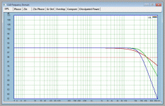
Red is 1st order, and Blue is 3rd order, but the easier one for you to implement is Green, the 2nd order.
So below and after, then next post will add additional comments.
So below and after, then next post will add additional comments.
Attachments
Last edited:
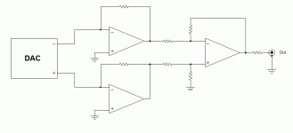
So the first is a bog standard 'Virtual Earth' I/V converter.
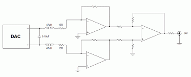
The second shows the added components, five per channel: Two resistors, two small chokes/inductors and a single capacitor.
I would recommend trimming the 0.18uF (or 180nF) down in value and aim for the flattest response at 20KHz. You might find that with 0.18uF it will be down a negligible 0.25dB, hardly a bad result, but some like 0.17uF or 170nF combination of parallel caps, will tweak the circuit.
But just try it with 0.18uF to get you started and if you like what it does, then tweak it.
The 47uH coils, we used some that was rated at 3A, so saturation is not going to be a problem.

We also unwrapped the wire and much less than a metre, we remade them with better wire, so that can also be a later tweak, but the coils did work standard quite well.
OK, up to you to try it. Cheers, Joe.
.
The second shows the added components, five per channel: Two resistors, two small chokes/inductors and a single capacitor.
I would recommend trimming the 0.18uF (or 180nF) down in value and aim for the flattest response at 20KHz. You might find that with 0.18uF it will be down a negligible 0.25dB, hardly a bad result, but some like 0.17uF or 170nF combination of parallel caps, will tweak the circuit.
But just try it with 0.18uF to get you started and if you like what it does, then tweak it.
The 47uH coils, we used some that was rated at 3A, so saturation is not going to be a problem.
We also unwrapped the wire and much less than a metre, we remade them with better wire, so that can also be a later tweak, but the coils did work standard quite well.
OK, up to you to try it. Cheers, Joe.
.
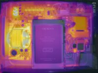
Facinating
That's one way to put a cool toy to use 🙂 Great Pic!
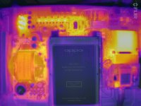
A "thermal" picture of my modified 203...
That's one way to put a cool toy to use 🙂 Great Pic!
Indeed. I actually intend to use this tool as a tool (less as a toy)... Here is only a cool example🙂
In the last time I redesigned and produced new side panels for 203. A better version of the improved ventilation approach for this device (with the linear PSU inside)...
Attachments
In the last time I redesigned and produced new side panels for 203. A better version of the improved ventilation approach for this device (with the linear PSU inside)...
As always, great job 🙂
I2S board that can be used in OPPO 103 and 203 is now developed.
With the HDMI type connector of PS AUDIO standard, DSD and SACD data as well as PCM file data can be transmitted to the outside via HDMI terminal conforming to PS AUDO standard.
The I2S signal from the main board is branched out simultaneously.
So that it goes to the internal DAC board on one side and the other to the outside.
The problem is that an HDMI type connector can not be mouned to the rear pannel of OPPO 203. In the near future, I m planning to produce a small amount of back panel that can mount HDMI Type I2s board and connector.
OPPO 103 and 203 can be selected with the jumper switch setting.
---
I know there is not much demand, but some people have been asking steadily.
In the future, however, there is an increasing number of external DACs capable receiving the sacd and DSD data streams. Most of them conform to the PS Audio specification.
If it is HDMI connector's pin placement is different, it is solved by specially making HDMI cable.
Been incredibly busy these last few months, not just the trip, but working on tube power amps and other stuff.
Now if we may harken back to an earlier topic of filtering DACs that Ken wanted to put a name to, that 'development' has not stood still.
We can now filter the Oppo's DACs (any of them) 2nd order and 3rd order, remember that slow 1st order filter couldn't be flat at 20KHz and that was a 'downer' with some, if you know what I mean?
So here is a comparison, it will take a few posts to intermingle the comments as I am unable to link to them online.
But below is the first one, the difference between the 3 orders:
Hey Joe,
Good to see you are doing what I recommended right from the outset - that is a higher order filter.
I think this was always the best solution and that's why most people use it.
The advantages are many fold.
a/ A single order filter is not linear phase. b/ a multi order can be linear phase right through the audio range c/ multi order has much better attenuation of high frequencies.
Once you have decided on a topology, make sure you run a 10kHz square wave through it, using same impedances as if driven by DAC. If it is linear
phase it will round the rising edge of nicely with no ringing or overshoot.
I think the implementation is the key. There are so many ways to implement
a filter like this. And as you have discovered, with higher order, the FR through audio band can be very flat but still achieve very good attenuation
past audio band.
T
- Home
- Source & Line
- Digital Source
- Oppo new UDP series players - 203/205 - Discussions, upgrades, modifications