Hi nezbleu,
sorry for confusion. GME is a Czech store GM electronic - elektronika, kterou znáte... and parts with their code are not critical. All resistors are metal film 1% 0.4 - 0.6W. CF3 is a MKP (polyester) capacitor. Arcotronics R66 preferably. C-5 means 5mm spacing, C-7.5 means 7.5mm spacing etc. Critical parts are FKP (polypropylene caps, WIMA) and parts from Farnell or RS components.
Sorry for another silly question... The 51 Ohm resistors (R3, 5, 9): is the value critical? Since some of them are in the signal path I am tempted to splurge on some nice parts (low tempco, low noise, tight tolerance for matching), and I can get 50R of the type I want to buy, but not 51R. Alternatively I can get some at 51R1 which look OK. I assume a 1 Ohm difference for R3 won't have a significant effect, but R5 and R9 are before and after the RIAA network. Would I be better off getting precisely 51R for those, or would 50R be OK?
Thanks.
The 51 ohm resistor are not critical.
The 51R1 you mentioned should be 51.1 ohms which is perfect. Buy a bunch and select the 51 ohm ones if you really wanna get crazy!
The 51R1 you mentioned should be 51.1 ohms which is perfect. Buy a bunch and select the 51 ohm ones if you really wanna get crazy!
51R resistor values are not critical at all 🙂. Important are resistors and capacitors in the feedback network, indexed 50 and above (150 and above).
Pavel,
Is it possible to get board dual mono(if not already built). Up to date , dual mono phono always sound better ! I really don't know why .... but ready to pay extra for.
Is it possible to get board dual mono(if not already built). Up to date , dual mono phono always sound better ! I really don't know why .... but ready to pay extra for.
I'm sure Pavel tested between channels and may even have a niffty graph but I think his design is at such a high level of technical performance that going full dual mono would be verrrrrry diminishing returns.
Besides, this is phono! What sort of separation, channel immunity, etc ... do you think you get from the cartridge? 😱
Also, Pavel is a busy guy and this type of audio is just his hobby ... I'm surprized he actually got the PCB up! 😉
Besides, this is phono! What sort of separation, channel immunity, etc ... do you think you get from the cartridge? 😱
Also, Pavel is a busy guy and this type of audio is just his hobby ... I'm surprized he actually got the PCB up! 😉
PCB Update?
I too would like to see a optional MC stage.
MLStrand56
Here we are at mid-Feb. Any update on the PCB's or kits?MLStrand56, not yet as a kit. But PCBs will be available by the end of January 2013.
I too would like to see a optional MC stage.
MLStrand56
PCBs for OPENAMP1 phono preamp are available. I am sorry but kits will not be available, at least not in near future like 6 months - 1 year. The time I can spend with audio is very very limited.
Pavel Macura audiopage
Pavel Macura audiopage
Crap! That didn't last long. The pricelist lists the PCB selling out on Feb 14!
Yikes, you snooze, you loose I guess.
I've emailed Pavel about a possible next order and will post his response.
Yikes, you snooze, you loose I guess.
I've emailed Pavel about a possible next order and will post his response.
I am sorry but I am completely occupied with work on industrial automation projects and plasma spraying. Thus, I really have not enough time for PCB production and distribution to customers, which is time consuming. I have offered the completely open project and I believe that it provides enough information for potential builders, even if they had to design their own PCBs. Sorry for any inconvenience.
Schematics and assembly instructions (in one document) and BOM may be downloaded for free from my webpage:
Preamplifier for MM cartridge
Schematics and assembly instructions (in one document) and BOM may be downloaded for free from my webpage:
Preamplifier for MM cartridge
Great - another new MM-preamp design!
Mmh? Maybe I misunderstand something here, but adjustable cartridge loading is simply mandatory to get great sound out of mm-cartridges. It certainly affects RFI filtering and such, but providing only a fixed load capacitance for all mm-cartridges is certainly the worse compromise, imho.
Do not add any capacitance.
Mmh? Maybe I misunderstand something here, but adjustable cartridge loading is simply mandatory to get great sound out of mm-cartridges. It certainly affects RFI filtering and such, but providing only a fixed load capacitance for all mm-cartridges is certainly the worse compromise, imho.
h_a, capacitive loading of MM cartridge is a sum of cable capacitance, C1 and C2. If you read the assembly instructions, you would find an answer there.
Cable capacitance + C2 would give something like 250pF. If it is not enough, then it is possible to use C1. BUT, in case that audiophiles omit to respect the cable capacitance and take into account only C1 + C2 capacitors, they would get too high load capacitance, resulting in resonance peak somewhere between 12 - 18 kHz. It may sound "interesting", I agree, but not correct.
Michael, thanks about info on receiving the shipment.
Last edited:
I built practically the same MM preamp ten years ago. It was based on LT 1115 app. note. Sound was good, but I soon replaced it with 1991 year Borbely phono , and improvement was amazing. All in all a good medium level preamp, not too complex, but not SOTA.
Only "practically" same.
LT1115 is not suitable for MM. No BJT input opamp is suitable for MM cartridges.
LT1115 is not suitable for MM. No BJT input opamp is suitable for MM cartridges.
Here's more explanation:
Yes it is similar, but for MM we preferably use JFET input opamps with reasonably low voltage noise, for the reason of almost no current noise added. Remember that above 1kHz the noise in MM preamp is dominated by the 47k standardized load resistor (just one comment here, reducing load resistance below 47k increases resulting noise!!!!!!! - for the reason of character of MM cartridge impedance). BJT opamps like AD797 are definitely the choice for MC preamps.
I did not use LT1115, I used NE5534 which is said to be ideal for MM impedances. Douglas Self uses it in his phono preamps for MM sections.Only "practically" same.
LT1115 is not suitable for MM. No BJT input opamp is suitable for MM cartridges.
Today, I would use OPA 134 which I use usually for DC servo circuits.
NE5534 is a BJT input opamp, OPA134 is a FET input opamp.
PMA:
For MM we prefer to use JFET input opamps with reasonably low voltage noise, for the reason of almost no current noise added. Remember that above 1kHz the noise in MM preamp is dominated by the 47k standardized load resistor ...for the reason of character of MM cartridge impedance.
The OPENAMP1 may look like an ordinary opamp RIAA but it has subtle details (including specific choice of opamp) that boost it's technical performance above the rest. The thread isn't too long ... just do a quick skim for all PMA's stuff, it's all there ...
Last edited:
Here's all the PMA bits for those just joining:
For those who might be interested, I have prepared an open project of the phono preamplifier for MM cartridge. It has very low noise and very low distortion. Gain is 40dB/1kHz. Output is capable to drive 50 ohm load, so one may directly connect headphones via 100 - 220 ohm pot.
The buffers make 2 or 3 improvements:
1) feedback network may use lower impedance resistors (100 ohm between -IN and GND) to get lower noise. This results in higher capacitances, that are easily driven with buffer.
2) buffered output is much less sensitive to output cable type and length.
3) output is able to drive headphones.
To demonstrate buffer capabilities, please see attached distortion measurement of this MM preamplifier into 50 ohm load.
The preamp is really "foolproof". If assembled with recommended components without mistakes in soldering, it works at first attempt, without any adjustment. The DC output offset is below 1mV.
But, the main contributor of the noise is NOT the preamplifier, but the vinyl groove itself. I have a plenty of measurements of noises of plain vinyl surface, "empty" ("silent") grooves, grooves "without signal" from measuring records etc. The real record would worsen the noise about 30 dB compared to the measurement of the preamp connected to the cartridge with needle "in the air". Please see one of the measurements of the vinyl groove "without signal". Especially the low frequency noise of the vinyl is quite horrible.
Let's see what happens with noise level when we replace the OPA627 with OPA134, TL071 and AD744. But, how much important is this considering the vinyl groove noise? It is up to the builder, but I still recommend the OPA627. For those who would like to use something cheaper I would admit to use the OPA134, but nothing worse. All these measurements with input teminated with 50 ohm.
something similar is done by R2 + C2 (at the input). This prevents the gain plot from remaining at 0dB at high frequencies. I want to maintain "strong" output, and the circuit works well even into 50 ohm or 32 ohm. 2nd reason not to add resistance is to keep 51 ohm output impedance (and thus low influence of interference in case one uses the 50 ohm coax.).
Anyway, it is the cartridge inductance that dominates in overall HF behavior.
All resistors are metal film 1% 0.4 - 0.6W. CF3 is a MKP (polyester) capacitor. Arcotronics R66 preferably. C-5 means 5mm spacing, C-7.5 means 7.5mm spacing etc. Critical parts are FKP (polypropylene caps, WIMA) and parts from Farnell or RS components.
Well, yes. As now, it serves mostly as an RFI filter.
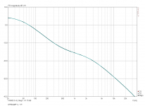
It might, theoretically, improve RIAA response for very high frequencies, if we speak about phono preamp alone, driven from pure voltage source. As you know, non-inverting network has gain no smaller than +1 (0dB), until the opamp's bandwidth will roll it off. R2 C2 could be calculated to allow the RIAA curve continue in attenuation even for very high frequencies above audio band. Please see the attached image.
But, in a real world the phono preamp amplifies signal not from the voltage source, but from MM cartridge, which has output impedance like resistance and inductance in series. Usually 500 ohm - 2000 ohm + 300 mH - 1500 mH. This inductance makes thus a roll-off even for high frequencies and the role of R2C2 described hereabove is valid only in case of voltage source signal (= zero output impedance). And we cannot increase C2 too much because we would load the cartridge by high capacitance and create high resonance peak somewhere between 15 - 20 kHz. We also cannot increase R2 too much for we would get increased noise.
I hope this helps a little, for more on theory please study literature about phono cartridges, like Vogel (The Sound of Silence). Walt Jung's publications are also excellent and may help, but I am not sure if he works with cartridge models in his considerations.
Yes it is similar, but for MM we preferably use JFET input opamps with reasonably low voltage noise, for the reason of almost no current noise added. Remember that above 1kHz the noise in MM preamp is dominated by the 47k standardized load resistor (just one comment here, reducing load resistance below 47k increases resulting noise!!!!!!! - for the reason of character of MM cartridge impedance). BJT opamps like AD797 are definitely the choice for MC preamps.
h_a, capacitive loading of MM cartridge is a sum of cable capacitance, C1 and C2. If you read the assembly instructions, you would find an answer there.
Cable capacitance + C2 would give something like 250pF. If it is not enough, then it is possible to use C1. BUT, in case that audiophiles omit to respect the cable capacitance and take into account only C1 + C2 capacitors, they would get too high load capacitance, resulting in resonance peak somewhere between 12 - 18 kHz. It may sound "interesting", I agree, but not correct.
😎
For those who might be interested, I have prepared an open project of the phono preamplifier for MM cartridge. It has very low noise and very low distortion. Gain is 40dB/1kHz. Output is capable to drive 50 ohm load, so one may directly connect headphones via 100 - 220 ohm pot.
The buffers make 2 or 3 improvements:
1) feedback network may use lower impedance resistors (100 ohm between -IN and GND) to get lower noise. This results in higher capacitances, that are easily driven with buffer.
2) buffered output is much less sensitive to output cable type and length.
3) output is able to drive headphones.
To demonstrate buffer capabilities, please see attached distortion measurement of this MM preamplifier into 50 ohm load.
The preamp is really "foolproof". If assembled with recommended components without mistakes in soldering, it works at first attempt, without any adjustment. The DC output offset is below 1mV.
But, the main contributor of the noise is NOT the preamplifier, but the vinyl groove itself. I have a plenty of measurements of noises of plain vinyl surface, "empty" ("silent") grooves, grooves "without signal" from measuring records etc. The real record would worsen the noise about 30 dB compared to the measurement of the preamp connected to the cartridge with needle "in the air". Please see one of the measurements of the vinyl groove "without signal". Especially the low frequency noise of the vinyl is quite horrible.
Let's see what happens with noise level when we replace the OPA627 with OPA134, TL071 and AD744. But, how much important is this considering the vinyl groove noise? It is up to the builder, but I still recommend the OPA627. For those who would like to use something cheaper I would admit to use the OPA134, but nothing worse. All these measurements with input teminated with 50 ohm.
something similar is done by R2 + C2 (at the input). This prevents the gain plot from remaining at 0dB at high frequencies. I want to maintain "strong" output, and the circuit works well even into 50 ohm or 32 ohm. 2nd reason not to add resistance is to keep 51 ohm output impedance (and thus low influence of interference in case one uses the 50 ohm coax.).
Anyway, it is the cartridge inductance that dominates in overall HF behavior.
All resistors are metal film 1% 0.4 - 0.6W. CF3 is a MKP (polyester) capacitor. Arcotronics R66 preferably. C-5 means 5mm spacing, C-7.5 means 7.5mm spacing etc. Critical parts are FKP (polypropylene caps, WIMA) and parts from Farnell or RS components.
Well, yes. As now, it serves mostly as an RFI filter.
It might, theoretically, improve RIAA response for very high frequencies, if we speak about phono preamp alone, driven from pure voltage source. As you know, non-inverting network has gain no smaller than +1 (0dB), until the opamp's bandwidth will roll it off. R2 C2 could be calculated to allow the RIAA curve continue in attenuation even for very high frequencies above audio band. Please see the attached image.
But, in a real world the phono preamp amplifies signal not from the voltage source, but from MM cartridge, which has output impedance like resistance and inductance in series. Usually 500 ohm - 2000 ohm + 300 mH - 1500 mH. This inductance makes thus a roll-off even for high frequencies and the role of R2C2 described hereabove is valid only in case of voltage source signal (= zero output impedance). And we cannot increase C2 too much because we would load the cartridge by high capacitance and create high resonance peak somewhere between 15 - 20 kHz. We also cannot increase R2 too much for we would get increased noise.
I hope this helps a little, for more on theory please study literature about phono cartridges, like Vogel (The Sound of Silence). Walt Jung's publications are also excellent and may help, but I am not sure if he works with cartridge models in his considerations.
Yes it is similar, but for MM we preferably use JFET input opamps with reasonably low voltage noise, for the reason of almost no current noise added. Remember that above 1kHz the noise in MM preamp is dominated by the 47k standardized load resistor (just one comment here, reducing load resistance below 47k increases resulting noise!!!!!!! - for the reason of character of MM cartridge impedance). BJT opamps like AD797 are definitely the choice for MC preamps.
h_a, capacitive loading of MM cartridge is a sum of cable capacitance, C1 and C2. If you read the assembly instructions, you would find an answer there.
Cable capacitance + C2 would give something like 250pF. If it is not enough, then it is possible to use C1. BUT, in case that audiophiles omit to respect the cable capacitance and take into account only C1 + C2 capacitors, they would get too high load capacitance, resulting in resonance peak somewhere between 12 - 18 kHz. It may sound "interesting", I agree, but not correct.
😎
Last edited:
- Home
- Source & Line
- Analogue Source
- OPENAMP1 - MM phono preamp open project