Maybe there is a misunderstanding, I have not said your OPA627 was a fake. I only would like to warn against cheap parts. It is based on experience that a colleague of mine bought 100 pcs of OPA627 at a very cheap price, and all fakes. There was completely different chip inside with different parameters. Yours looks OK, but it may be hard to tell from the photo. Unfortunately I do not remember who was the seller of the fakes, I will try to find out.
Thanks ALD, your eyes are better than mine! That was pretty much what I assumed. With the right type and lead spacing I should be able to source everything from multiple vendors.
..It is based on experience that a colleague of mine bought 100 pcs of OPA627 at a very cheap price, and all fakes. There was completely different chip inside with different parameters...
I'm sure mine are fine as I got them a long time ago from reputable sources however others might want to know ...
Anyway back to OPENAMP1
PMA knows this (because he's always going ooooon and ooooon about EMI! ;-) ) but others might not:

😱

😱
http://www.ti.com/lit/an/sboz016a/sboz016a.pdf
PMA could you talk more about your interesting R2(150ohm)/C2(100pF) filter (10MHz) right at the input? I wonder what that could be about ... 😎
Cheers,
Jeff
PS "EMI and OPA627" could be it's own thread too! Application outside of RIAA ...
Next, when PMA has the time, perhaps he could talk more about the other interesting aspect of his input stage: diodes

Would it have something to do with "diode clamping":

From:
http://www.ti.com/lit/an/sboa011/sboa011.pdf
Or are the diodes for safety ...
Cheers,
Jeff
Would it have something to do with "diode clamping":
From:
http://www.ti.com/lit/an/sboa011/sboa011.pdf
Or are the diodes for safety ...
Cheers,
Jeff
Last edited:
re: diodes
diodes to the rails like that are usually done for protection against transients
mlloyd1
diodes to the rails like that are usually done for protection against transients
mlloyd1
jeff:
see post #33
btw, for the new folks, you can get some good discussion of somewhat similar and other RIAA preamp designs in ADI "app note" here
note: big file but definitely worth downloading and study.
see post #33
...
PMA could you talk more about your interesting R2(150ohm)/C2(100pF) filter (10MHz) right at the input? I wonder what that could be about ... 😎
btw, for the new folks, you can get some good discussion of somewhat similar and other RIAA preamp designs in ADI "app note" here
note: big file but definitely worth downloading and study.
PMA could you talk more about your interesting R2(150ohm)/C2(100pF) filter (10MHz) right at the input? I wonder what that could be about ... 😎
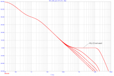
Well, yes. As now, it serves mostly as an RFI filter.
It might, theoretically, improve RIAA response for very high frequencies, if we speak about phono preamp alone, driven from pure voltage source. As you know, non-inverting network has gain no smaller than +1 (0dB), until the opamp's bandwidth will roll it off. R2 C2 could be calculated to allow the RIAA curve continue in attenuation even for very high frequencies above audio band. Please see the attached image.
But, in a real world the phono preamp amplifies signal not from the voltage source, but from MM cartridge, which has output impedance like resistance and inductance in series. Usually 500 ohm - 2000 ohm + 300 mH - 1500 mH. This inductance makes thus a roll-off even for high frequencies and the role of R2C2 described hereabove is valid only in case of voltage source signal (= zero output impedance). And we cannot increase C2 too much because we would load the cartridge by high capacitance and create high resonance peak somewhere between 15 - 20 kHz. We also cannot increase R2 too much for we would get increased noise.
I hope this helps a little, for more on theory please study literature about phono cartridges, like Vogel (The Sound of Silence). Walt Jung's publications are also excellent and may help, but I am not sure if he works with cartridge models in his considerations.
Attachments
Last edited:
It is based on experience that a colleague of mine bought ....
I have some additional info, it was 2 years ago and "OPA627's" were in TO-99 metal cans and they had input bias current several orders higher than specified in the datasheet. So he did not use them and started complaints/warranty return procedure. I agree that in case of discussion on this subject we should start a separate thread, but I cannnot promise I would be able to spend much time there.
Now, I just got into vinyl a couple of months ago, so correct any newbie mistakes ...
I've looked at cart loading before for I didn't include the inductance ...
Wow PMA you weren't kidding! Totally different!
Ortophon tells me my OM5E has:
Internal impedance, DC resistance 750 Ohm
Internal inductance 450 mH
And recommends 200-600pF/47k loading (300pF/47k)
I threw those into the Tina circuit of the 627 and then added just the input of the OPENAMP1:
View attachment OPA627 PMA riaa input.zip
Had to zip it, hope it unzips ok
And then simmed (1 to 100k) with the RF filt (150/100pF)

3.4dB boost at 10.2k
And then simmed with no RF filt

2.4dB boost at 10.9k
I didn't think it would matter being a 10Mhz filter but I guess it interacts with all the other input parameters:

So a 3.4dB boost at 10.2k with the RF filter but only a 2.4dB boost at 10.9k with out! Wow, wasn't expecting that ... but it is a small difference.
Hmmmm
...But, in a real world the phono preamp amplifies signal not from the voltage source, but from MM cartridge, which has output impedance like resistance and inductance in series. ...
I've looked at cart loading before for I didn't include the inductance ...
Wow PMA you weren't kidding! Totally different!
Ortophon tells me my OM5E has:
Internal impedance, DC resistance 750 Ohm
Internal inductance 450 mH
And recommends 200-600pF/47k loading (300pF/47k)
I threw those into the Tina circuit of the 627 and then added just the input of the OPENAMP1:
View attachment OPA627 PMA riaa input.zip
Had to zip it, hope it unzips ok
And then simmed (1 to 100k) with the RF filt (150/100pF)
3.4dB boost at 10.2k
And then simmed with no RF filt
2.4dB boost at 10.9k
I didn't think it would matter being a 10Mhz filter but I guess it interacts with all the other input parameters:
So a 3.4dB boost at 10.2k with the RF filter but only a 2.4dB boost at 10.9k with out! Wow, wasn't expecting that ... but it is a small difference.
Hmmmm
Last edited:
Yes, but you would need to sim the whole circuit, to get the correct answer. This was done, for various Rs, Ls, R2 and C2.
And with 500pF/47k as cart load (the high end of the recommended capacitance)
With RF filt:
4.7dB @ 8.7k
Without RF filt:
4.1dB @ 9.3k
Hmmm....
PS I was trying to isolate the input circuitry and see what it does ... and unfortunately TINA doesn't have an LT1010 model :-(
With RF filt:
4.7dB @ 8.7k
Without RF filt:
4.1dB @ 9.3k
Hmmm....
PS I was trying to isolate the input circuitry and see what it does ... and unfortunately TINA doesn't have an LT1010 model :-(
Last edited:
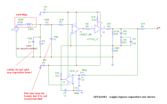
Do not add any capacitance. Please see that additional input capacitor is zero in the BOM. Keep only C2, indexed as per my schematics. Your different indexes are confusing the issue and may be misleading for other readers. Please do not modify the part values if building the preamp.
Last edited:
Sorry Pavel, you were right. 😱
Simming the rest of circuit isolated the RF filter from loading the cartridge.
Ok, no C1 capacitor and just assume 150pF as the value to account for cable capacitance. I've updated my circuit.
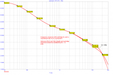
With the RF filt (R2=150ohm, C2=100pF) there's a difference at 50MHz:
With RF filt

5MHz @ -195dB
Without RF filt

5MHz @ -180dB
TINA didn't have LT1010 but it did have BUF634 so I used that just to see the basic frequency response. Here's the TINA circuit with the BUF634.

And the TINA file:
View attachment PMA riaa OPA627 BUF634.zip
Anyone know where to get a LT1010 TINA model? I think there's a LTspice4 model of the 1010 ... how to import ...
PS Sorry for screwing up your thread, I've corrected all the typos I think ...
Simming the rest of circuit isolated the RF filter from loading the cartridge.
Ok, no C1 capacitor and just assume 150pF as the value to account for cable capacitance. I've updated my circuit.
With the RF filt (R2=150ohm, C2=100pF) there's a difference at 50MHz:
With RF filt
5MHz @ -195dB
Without RF filt
5MHz @ -180dB
TINA didn't have LT1010 but it did have BUF634 so I used that just to see the basic frequency response. Here's the TINA circuit with the BUF634.
And the TINA file:
View attachment PMA riaa OPA627 BUF634.zip
Anyone know where to get a LT1010 TINA model? I think there's a LTspice4 model of the 1010 ... how to import ...
PS Sorry for screwing up your thread, I've corrected all the typos I think ...
Last edited:
You will get the same sim results for buf634 and lt1010 regarding freq response. Please keep C1 = 0 and C2 = 100p, as written in the manual and the bom.
Linear Technology had a similar circuit many years ago for their LT1115. I was surprised it is still on the LT website. Here it is. LT1115 - Ultra-Low Noise, Low Distortion, Audio Op Amp - Linear Technology
Ray
Ray
Here's the TINA circuit with 627, BUF634, OP07:

And the TINA file:
View attachment PMA riaa OPA627 BUF634 wservo.zip
I found a LT1010 spice model and tried to import it but it peaked the freq response?!? 😕
http://cds.linear.com/docs/en/software-and-simulation/LT1010.txt
And the TINA file:
View attachment PMA riaa OPA627 BUF634 wservo.zip
I found a LT1010 spice model and tried to import it but it peaked the freq response?!? 😕
http://cds.linear.com/docs/en/software-and-simulation/LT1010.txt
I think I got it! I successfully imported the LT1010 spice file and assigned some pins ...
OPENAMP1 TINA schematic

Frequency Response 20-30k

And TINA file
View attachment PMA riaa OPA627 LT1010 OP07.zip
OPENAMP1 TINA schematic
Frequency Response 20-30k
And TINA file
View attachment PMA riaa OPA627 LT1010 OP07.zip
Last edited:
Linear Technology had a similar circuit many years ago for their LT1115. I was surprised it is still on the LT website. Here it is. LT1115 - Ultra-Low Noise, Low Distortion, Audio Op Amp - Linear Technology
Ray
Yes it is similar, but for MM we preferably use JFET input opamps with reasonably low voltage noise, for the reason of almost no current noise added. Remember that above 1kHz the noise in MM preamp is dominated by the 47k standardized load resistor (just one comment here, reducing load resistance below 47k increases resulting noise!!!!!!! - for the reason of character of MM cartridge impedance). BJT opamps like AD797 are definitely the choice for MC preamps.
- Home
- Source & Line
- Analogue Source
- OPENAMP1 - MM phono preamp open project