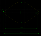
Here's a drawing for a nicer clamp to fix the R2904 to the waveguide. A 3mm aluminium plate should be fine.
Edit: added a CAD file for use with Front Panel Designer, so you can order the clamp directly from Schaeffer or Front Panel Express (ZIP file).
Edit: added a CAD file for use with Front Panel Designer, so you can order the clamp directly from Schaeffer or Front Panel Express (ZIP file).
Attachments
Last edited:
Cool!
Super simple just to fab from sheet stock I have here too. Probably want some interface material, rubber etc, between the back of the tweeter and the clamp? Am I visualizing that correctly?
Super simple just to fab from sheet stock I have here too. Probably want some interface material, rubber etc, between the back of the tweeter and the clamp? Am I visualizing that correctly?
Hmm, I wrote a reply yesterday, but it seems it disappeared somehow. Anyways, long story short: yes you are visualizing this correctly 🙂
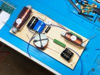
Oh yes... Just messing about with Xover roughout to make sure all the parts are accounted for... Pic is a little bit clear, haha—Haven't cut anything of course. Will be tightened up when I actually break out the soldering iron.... but everything is semi-oriented per the awesome build notes. Woofer, mid, tweeter....Will fit on 12x6" plates or less if I can manage. Not sure how much space is really ideal around all the coils...
Yea!

Yea!
Attachments
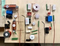
That already looks quite good!
Woofer section: try to increase the distance between the inductors a bit more. Those large inductors are sensitive to crosstalk.
Mid section: rotate the 0.33 mH inductor so it's perpendicular to the nearby inductors. You might also rotate the 2.7 mH inductor.
Woofer section: try to increase the distance between the inductors a bit more. Those large inductors are sensitive to crosstalk.
Mid section: rotate the 0.33 mH inductor so it's perpendicular to the nearby inductors. You might also rotate the 2.7 mH inductor.
I think your original woofer layout was better—Gets a little snaky there at W+.
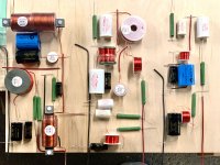
Should .10mH also flip up? (Probably not for tweeter in center of box arrangement and where it seems it might interact with tweeter LT1?)
The plan was to follow your box arrangement with the tweeter on the floor of the box and woofer and mid, left and right respectively.
Hoping for a plinth with exterior dims around 10x14", angled up about an inch 6" at back, 7" or so at front...Maybe overall a bit taller since I will have to account for the floor of the box... Does there need to be airflow in a crossover box?
Attachments
Should .10mH also flip up?
Yeah, why not.
Does there need to be airflow in a crossover box?
Naaah.
Maybe a dumb question but................
Do people have any alternative ideas about where to place their Xover boards apart from in the bottom of the enclosure? Various things come to mind ie. In a box attached to the back, in a chamber below the main volume of the enclosure accessible from behind, in a separate box or in the open air etc. Any thoughts on practicality vs aesthetics
Do people have any alternative ideas about where to place their Xover boards apart from in the bottom of the enclosure? Various things come to mind ie. In a box attached to the back, in a chamber below the main volume of the enclosure accessible from behind, in a separate box or in the open air etc. Any thoughts on practicality vs aesthetics
My xovers are in a box behind the rack where my audio gear is (so the box is invisible except if you crawl behind the rack). I use a single 8 x Speakon cable to connect the xover to the Monkey Coffin (2 wires for the tweeter, 2 for the midrange, 2 x 2 for the woofer). Nothing that might be considered as "not aesthetic".
Maybe a dumb question but................
Do people have any alternative ideas about where to place their Xover boards apart from in the bottom of the enclosure? Various things come to mind ie. In a box attached to the back, in a chamber below the main volume of the enclosure accessible from behind, in a separate box or in the open air etc. Any thoughts on practicality vs aesthetics
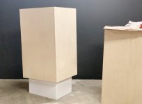
I'm doing exactly one version of what you are stating above—My crossovers will be in a plinth below the speaker cab. Roughly 10x14x7" max ext dimensions—with a 1" drop to the back for a little up angle. Speakon connection between the main cabinet and crossover plinth, then regular binding posts to receive from amp.
I may have pics later today.
Last edited:
Both of those ideas sound good to me. Reassuring to find I'm not the only one thinking "outside the box".
Oh man!
WAVEGUIDES!!!!!!! Thanks Matthias! Beautiful. See shot of a "low" profile M4 bolt. McMastercarr here in US sells more or less 3 head profiles... the "extra-low" they want around $5 PER BOLT! I just couldn't do it... but, I think the "low's" will look fine (Until they bother me enough that I change them at some point ;-). It does seem like you could mod the CAD a hair and make the head sink another 1.5mm... just a thought! I see some taps for a clamp rig—so that may affect my plan.
Having the best time working out the crossovers. Is there a preferred method for more or less butt joining bigger gauge wires? I have a lot of 14/3 house cable that I was gonna use for the main pos/neg runs... open to advice/thoughts of course.
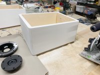
In the end the "stance" of the crossover boxes is about a 3/4" drop. Working out the white finish process—which will be super matte in the end...I think the crossover plinth a great solution personally—aids the WAF factor. They won't be attached to the cabinet. I'll line the top edge with some felt for grip. The long edges of the baffle will get the same roundover. In the end I have decided to make grills. So there will be magnets embedded and bondo filled. The audiohobby guys/suppliers in Estonia have German made speaker grill cloth. The white is very nice.
Give me perhaps another 2-3 weeks and these will be online... no promises though. The world has gone crazy here—and I recently got the PSU for my Aikido preamp working...
YEA!

WAVEGUIDES!!!!!!! Thanks Matthias! Beautiful. See shot of a "low" profile M4 bolt. McMastercarr here in US sells more or less 3 head profiles... the "extra-low" they want around $5 PER BOLT! I just couldn't do it... but, I think the "low's" will look fine (Until they bother me enough that I change them at some point ;-). It does seem like you could mod the CAD a hair and make the head sink another 1.5mm... just a thought! I see some taps for a clamp rig—so that may affect my plan.
Having the best time working out the crossovers. Is there a preferred method for more or less butt joining bigger gauge wires? I have a lot of 14/3 house cable that I was gonna use for the main pos/neg runs... open to advice/thoughts of course.
In the end the "stance" of the crossover boxes is about a 3/4" drop. Working out the white finish process—which will be super matte in the end...I think the crossover plinth a great solution personally—aids the WAF factor. They won't be attached to the cabinet. I'll line the top edge with some felt for grip. The long edges of the baffle will get the same roundover. In the end I have decided to make grills. So there will be magnets embedded and bondo filled. The audiohobby guys/suppliers in Estonia have German made speaker grill cloth. The white is very nice.
Give me perhaps another 2-3 weeks and these will be online... no promises though. The world has gone crazy here—and I recently got the PSU for my Aikido preamp working...
YEA!
Attachments


Hey, this looks like you're enjoying your time in the workshop! Good stuff!
Don't loose your sleep over the xover wiring. I have no clue about the US way of specifying wire size, but as long as it's not much thinner than the leads of the xover parts you should be fine.
Don't loose your sleep over the xover wiring. I have no clue about the US way of specifying wire size, but as long as it's not much thinner than the leads of the xover parts you should be fine.
This is helpful Matthias. I was pretty much following the parts as a gauge for wiring (no pun intended).
Last edited by a moderator:
Here’s some ideas. Both metric and SAE. Bolt Depot has lots more choices and usually very reasonable prices. We use them in the store kits
Socket button head, Stainless steel 18-8 black oxide finish - Bolt Depot
Socket button head, Alloy steel black oxide finish - Bolt Depot
Metric socket button head, Class 12.9 alloy steel black oxide finish - Bolt Depot
Socket button head, Stainless steel 18-8 black oxide finish - Bolt Depot
Socket button head, Alloy steel black oxide finish - Bolt Depot
Metric socket button head, Class 12.9 alloy steel black oxide finish - Bolt Depot
Last edited:
This style/type are the perfect bolt for the waveguide as is however—if flat and exact is your thing:
McMaster-Carr
They would be perfectly flush—not finding them on bolt depot. Could also check Fastenal though...
McMaster-Carr
They would be perfectly flush—not finding them on bolt depot. Could also check Fastenal though...
Yeah, not on Bolt Depot. If the holes in the tweeter and waveguide were countersunk there are lots of possible bolts. Or people could use countersunk bolts in the existing holes but I understand that only a thin circle of contact might not be what you want. Probably perfectly fine though...
Socket flat head, Stainless steel 18-8 black oxide finish - Bolt Depot
Socket flat head, Stainless steel 18-8 black oxide finish - Bolt Depot
- Home
- Loudspeakers
- Multi-Way
- Open Source Monkey Box