Remark that changing resistors in the xo to adapt levels, also affects the curve shape (and sound), because the resistive load on the filter does change. In that way it is more recommended to use L-pads (if possible).
Yes, I am aware of this.
With the current filter design, there are two attenuation resistors in each filter branch, one before and one after the filter. Playing with both values allows changing the overall attenuation without changing the shape of the transfer function. Doing this is relatively easy in Vituix.
Last edited:
If the various ports are creating issues, could this perhaps be remedied by using passive radiators instead?
Last edited:

Here are the measurements of the two ScanSpeak tweeters on a few of my designs and Visiton WG148:
https://www.diyaudio.com/forums/mul...aveguides-cnc-3d-printing-34.html#post5751133
https://www.diyaudio.com/forums/mul...aveguides-cnc-3d-printing-34.html#post5751133
Here are the measurements of the two ScanSpeak tweeters on a few of my designs and Visiton WG148:
https://www.diyaudio.com/forums/mul...aveguides-cnc-3d-printing-34.html#post5751133
The results from your custom waveguides look great! I am tempted!
Here are my thoughts:
- The SPL response of the Scan R2904+WG148 response curves shown in augerpros post look pretty bad. Things look much better if the WG148 is machined to properly fit the R2904 (see here).
- Still, changing the Monkey Coffin from the WG148 waveguide to one of those custom designs might allow an even smoother SPL response at the top end. Some (minor?) changes of the x-over might be required.
- We want to keep the workshop difficulty on the "kitchen table" level. Fitting the custom waveguides to the Scan tweeter would be straight forward, while the WG148 requires some machining (see here and here). However, routing the tweeter cutout for the the elliptical shape of the custom waveguides might be slightly more difficult than with the circular WG148. I am not sure which is more in line with the "kitchen table" approach.
- The WG148 is easily available, while the augerpro waveguides need to be custom made on a 3D printer or a CNC machine. Then again, it's not difficult to upload augrerpros 3D files to an online service that does 3D printing or CNC and click the "order" button (just a bit more expensive, but not much compared to the costs of the other parts). I am currently drooling over a black anodized aluminium version of the augerpro custom waveguides at 3Dhubs.com.
What do you guys think? Stick to the WG148 or change to the augerpro waveguide for the Monkey Coffin?
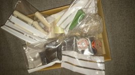
The postman brought some more x-over parts. Still missing some parts, but I got all for the tweeter filter and I quickly built it. The measured voltage gain is spot on with the Vituix model. Looks like the Vituix model output is pretty accurate!
Attachments

Last edited:
The postman brought the missing parts to finish the x-over, so I took the day off and finished building the filter prototypes. I am sorry, but I couldn't do any measurements or photos yet. I was busy with listening and dancing to the music (I rarely do that in the workshop!). According to my ears, this is coming along really well... stay tuned!
Ok, I sobered up a bit.
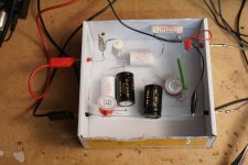
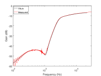
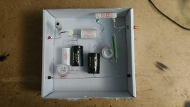
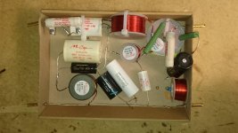
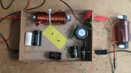
Here are some photos of the filter sections for the woofer, midrange and tweeter. I also attached the measured filter transfer curves and compared them with the curves of the Vituix model for the Monkey Coffin. The agreement between the observed and modelled curves is extremely good, almost spooky!
The only real issue I had was that the woofer transfer function did not look right at the beginning. Then I realised there was substantial crosstalk between the two large inductors, which were sitting just next to each other. Once I separated them from each other, things looked good. This is something to remember for the future, and it's especially important with steep filter slopes.
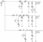
I also attached the filter circuit (this is version MB20190303_EL34).
Here are some photos of the filter sections for the woofer, midrange and tweeter. I also attached the measured filter transfer curves and compared them with the curves of the Vituix model for the Monkey Coffin. The agreement between the observed and modelled curves is extremely good, almost spooky!
The only real issue I had was that the woofer transfer function did not look right at the beginning. Then I realised there was substantial crosstalk between the two large inductors, which were sitting just next to each other. Once I separated them from each other, things looked good. This is something to remember for the future, and it's especially important with steep filter slopes.
I also attached the filter circuit (this is version MB20190303_EL34).
Attachments
-
 filter_gain_model_vs_meas.png34.9 KB · Views: 732
 -
 MB20190303_EL34_tweeter.jpg559.3 KB · Views: 701
 -
 MB20190303_EL34_midrange.jpg726.2 KB · Views: 688
 -
 MB20190303_EL34_woofer.jpg716.1 KB · Views: 687
 -
 lowpass_inductor_positions.png42.4 KB · Views: 694
 -
 MonkeyCoffin_MB20190303_EL34_XO-schema-1.png31.4 KB · Views: 305
That's ok! 🙂 So typical for the elliptical filters, they show the rhythm very well.I was busy with listening and dancing to the music
It's been quiet around here... I thought it might be useful to summarise the status quo of the Monkey Coffin design. We have not yet ironed out every little detail, but we have come very far with the Monkey Coffin. The prototype is working really well, and it wouldn't be wrong to say that we're done with working out the basics of the design. There are still a few things (and some loose ends) that can be implemented in different ways.
Here's my view (and I hope you guys will add your thoughts and ideas):
Are there any other parts of the design that need further work? Did I miss anything important?
The money we collected to build the prototype is used up (wood, x-over parts, damping materials, etc.; I added a few bucks from my own pockets).
I have also started writing up some documentation for the Monkey Coffin. It's publicly available on github, so that everyone can work on it. If you want to contribute, let me know your github user name so that I can add you to the contributors on github.
Here's my view (and I hope you guys will add your thoughts and ideas):
- x-over: we have focused on finalizing the elliptic filters, which are built and working very well. There is still the option of trying the "conventional" filters, which we designed in Vituix/LEAP and tested in the DSP processor. My experience with implementing the elliptic filters (Vituix -> DSP -> final passive circuit) was that the Vituix+DSP provided an extremely good "forecast" of the final passive filter, so I am confident that building the "conventional" filter designed in Vituix would work exactly as expected. The advantage of the "conventional" filter is that the circuit is slightly less complex, but not by much.
- Implementation of the bassreflex tuning/port: we had some heated debates about the best ways of implementing the bassreflex ports. I have my own opinion about this, which was largely guided by the tests I made with the prototype box. Other options also work, and it's possible to implement some of these without changing other parts of the design. Builders can freely choose if they prefer font or rear ports, or if they prefer round or slot ports. As long as the general bass tuning is not changed substantially, no changes to the x-over (or other parts of the design) are required. I'd therefore suggest to leave the decision about the position and geometry of the port to the builders of the Monkey Coffin.
- Waveguide (tweeter): the WG148 works very well with the Scan R2904 tweeter, but it's a bit of work to make it fit to the tweeter. I ordered a bunch of the augerpro waveguides, which should easily fit the R2904. This waveguide might be an option to make it easier to build the Monkey Coffin "on a kitchen table", and it might also change the audio performance. I will test this once I have the augerpro waveguides in my hands.
Are there any other parts of the design that need further work? Did I miss anything important?
The money we collected to build the prototype is used up (wood, x-over parts, damping materials, etc.; I added a few bucks from my own pockets).
I have also started writing up some documentation for the Monkey Coffin. It's publicly available on github, so that everyone can work on it. If you want to contribute, let me know your github user name so that I can add you to the contributors on github.
Matthias, it is not clear for me, you still have only one prototype playing at this moment?
If this is the case, in my opinion you cannot make a complete evaluation of the current design. I especially think at the sound spatial image of a stereo setup.
With a stereo set you also get a better impression of the power response of the speaker, how it is playing in a room...
Concerning the power response calculated by Vituix for the tweeter, there are some question marks/uncertainties for me. How is the tweeter power determined? Is the use of the waveguide taking into account?
As we know, using a waveguide, the power radiated by the tweeter in space will become lower for the same SPL on axis, because the tweeter power is more focussed on axis by the waveguide. Is this included in the Vituix power response?... that is my question mark...
Matthias, it is not clear for me, you still have only one prototype playing at this moment?
If this is the case, in my opinion you cannot make a complete evaluation of the current design. I especially think at the sound spatial image of a stereo setup.
With a stereo set you also get a better impression of the power response of the speaker, how it is playing in a room...
This is a very valid point. Yes, the prototype is still only one box. My idea was that I will build a stereo pair soon, once the decision about the waveguide is taken (WG148 vs augerpro). My assumption is that if any changes would be required after building a stereo pair, they would most likely be related to the filters (no more changes of the drivers or the box dimensions).
Concerning the power response calculated by Vituix for the tweeter, there are some question marks/uncertainties for me. How is the tweeter power determined? Is the use of the waveguide taking into account?
As we know, using a waveguide, the power radiated by the tweeter in space will become lower for the same SPL on axis, because the tweeter power is more focussed on axis by the waveguide. Is this included in the Vituix power response?... that is my question mark...
Vituix does not use any modelling to determine the off-axis response for the calculation of the power response. The power response is calculated as a weighted sum of the measured response curves (on-axis, off-axis). The weighting is described in the manual (page 22). The effects of the waveguide are therefore fully taken into account.
I agree, evaluation of a stereo pair only needs X-over tuning maybe.
Before finalizing the design you should need a stereoset...
I had made the assumption Vituix calculates the power like that, based on off axis measurements. In that way the calculated power is not exactly representative for the full space power, like is mentioned in the manual also.
IMO opinion it is better to look to the full space power for evaluation of the expected sound in a room.
Leap calculates the full space power using the driver model. That means the calculated power in Leap is the same with and without the waveguide, like it is in fact.
Using the full space power, the impact of the waveguide on the power can be observed.
I am not sure if I will use a tweeter waveguide for my own designs. I find it important that a speaker will fill the complete room (and even the house) with music, not only on the listening position. But that is a choice you have to make for yourself .
An advantage of the waveguide is the better matching off axis responses of the drivers, for a large midrange and a tweeter. In such system the full space power becomes lower at a few kHz.
I prefer a smaller midrange and a tweeter without waveguide with an x-over point not too high.
Designing for the best full space power, a waveguide had not been needed for the Monkey box. I shall post some plots later of the full space power of the Monkey Box with and without waveguide.
Some thought about the power response of the Monkey Box design.
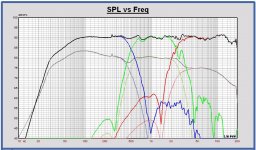
I have simulated the full space power in Leap of Matthias’ last EL34mix design (post 813). Compared with the Vituix power simulations the high frequency full space power is lower. This is caused by the power in Vituix that is calculated out of the frontal measured off axis SPL curves. The power response is smooth, but at the expense of a slight SPL fall off to high frequencies.
In the plots, the lower curves are the power curves.
A more flat SPL design, for example my first EL3 design proposal, will become difficult with the tweeter waveguide. You can see in the plot that the power response is not smooth anymore above 1 kHz.
Also added the tweeter SPL with and without waveguide. The difference between the curves is also the power difference for a flat SPL design with or without waveguide.
I have the opinion that with this midrange-tweeter driver choice, it would be better maybe to not use the tweeter waveguide. The reason is the midrange that is only 3 inch with a lot of power up to 3 kHz. The transition of the full space power to the tweeter with waveguide is not so good. With the waveguide it isn’t possible anymore to make a combined flat SPL – flat full space power design for higher frequencies.
It is a design choice, with a different sound, with or without the waveguide. ATC and Yamaha with similar driver choices don't use tweeter waveguides.
Attachments

I have simulated the full space power in Leap of Matthias’ last EL34mix design (post 813).
I agree that conceptually the LEAP and Vituix model results cannot be the same, since LEAP sums up the off-axis response in full space, whereas Vituix uses half space only. I wonder how accurate the LEAP dispersion model is as opposed to the true/measured SPL curves (as used in Vituix). Both the midrange and the tweeter use a waveguide. In addition, the tweeter is a ring radiator rather than a dome, which results in stronger beaming at high frequencies. I would think that effects of the waveguides and the ring tweeter might upset the modelled off-axis SPL responses, which are are summed using angular weighting to determine the power response. I guess that both LEAP and Vituix have their issues here. Is there a way to get some more insight to this?
The power response is smooth, but at the expense of a slight SPL fall off to high frequencies.
The fall-off is actually intentional. A sight fall off of the power response to high frequencies seems to be preferred by most listeners. See here and here, for instance.
Also added the tweeter SPL with and without waveguide. The difference between the curves is also the power difference for a flat SPL design with or without waveguide.
The SPL curve without the waveguide is probably the one from the Scan Speak datasheet, right? I'd guess this was measured on an IEC baffle, so it would be rather different to the curve we'd observe on the Monkey Coffin baffle.
I have the opinion that with this midrange-tweeter driver choice, it would be better maybe to not use the tweeter waveguide. The reason is the midrange that is only 3 inch with a lot of power up to 3 kHz. The transition of the full space power to the tweeter with waveguide is not so good.
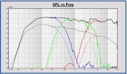
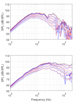
I am not sure. Take a look at the attached SPL curves (same data is in earlier posts, just a new plot). These are the measured on-axis and off-axis SPL curves of the midrange (upper panel) and the tweeter (lower panel), measured from -90° to +90° at 15° intervals. The SPL variation of the midrange at 2 kHz is about 12 dB (ok, it's a bit tricky to say, because of the notch present in the near-axis curves). For the tweeter, the SPL variation is about 10-12 dB at the same frequency. I'd say the dispersion of the tweeter and the midrange is very similar. Without the tweeter waveguide, the dispersion of the tweeter at 2 kHz would be much less, and it would not fit the midrange at all.
With the waveguide it isn’t possible anymore to make a combined flat SPL – flat full space power design for higher frequencies.
It is a design choice, with a different sound
While I was playing with the DSP filters, I tried a few iterations of x-over versions that gave flat on-axis SPL, while the power response (from the Vituix model) was not linear. This sounded overly bright, definitely not good. Once I decided to put the priority on the linearity of the power response with a slight fall off to high frequencies, the sound was much more balanced. This is why I decided to compromise the on-axis SPL curve in favour of a smooth power response.
So, yes, it is a design choice. Waveguides will for sure not always be a good choice. It certainly is possible to design a good monkey coffin type speaker without using waveguides, but that would be a different beast than the Monkey Coffin design we have developed here. I do think that in the current design the tweeter waveguide nicely allows for smooth dispersion at the the mid/tweeter x-over. In addition, the waveguide also helps to reduce tweeter distortion (because the drive voltage is lower), it helps reducing the baffle edge effects (because the beaming reduces sound at the baffle edges; the attached graphs show very little edge diffraction!), and it inherently adjusts the acoustic center of the tweeter with that of the midrange (ok, the nice match with the WG148 waveguide was just coincidence).
Finally, I think it's interesting to design a speaker that has some "built-in" beaming. In a somewhat simplified view one could say that the listener hears proportionally more direct sound from the speaker and less reverberant sound from the room, making the sound less dependent on the room and furnishing. Choices, choices, choices...
Attachments
- Home
- Loudspeakers
- Multi-Way
- Open Source Monkey Box