Sorry about the bump.
I will try and keep my thoughts to myself, maybe I will have to make a separate Monkey Box thread when the time is right for a new semi compact speaker in my house. It will be a 2way though. Single 12" + a 2 to 4" FR.
I will try and keep my thoughts to myself, maybe I will have to make a separate Monkey Box thread when the time is right for a new semi compact speaker in my house. It will be a 2way though. Single 12" + a 2 to 4" FR.
Thanks your thoghts Kaffimann, now ported designs is not my field but think discussions had been interesresting and guess what kind of explode here is your passion about sharing experience for research work into speaker building and sound of what your noticed there is not taken for good or too difficult to implement, in my view you can be right and noticed how many instruments or voices start their tones down there and timing plus smoothness to higher harmonics can be important if we wonna improve on the usual resolution we used to into those very difficult bands, difficult because room also rule down there so probably easy to conclude or misconclude on what is what in relation to designs.
I will try and keep my thoughts to myself...
Naaah. You're part of the gang! Your opinions are your opinions, and others are free to disagree. Those discussions help to shape the project, and allow us to make well founded decisions.
Byrtt, yes, lots of fundamentals down low are just plain wrong in many otherwise great sounding systems. And I think that a lot of tthe information we use to interpret spatial surroundings, is based on very low frequencies. Get it right, and you are "transported" to the recording location, feel the walls, the height of the ceiling et cetera.
A well founded decision is not based on the opinion of a single eccentric.
I have good capacity for abstract thought, does not mean I am right in anything at all.
Don't want to derail the thread into more off-topic.
Anyway, I am worried that having the port on the back might limit placement, and therefore also amount of potential builders, for this wonderful design, the 3way MonkeyBox.
Are you designing with rounded front to lower diffraktions?
No. We've had this discussion several times now. Please look for the corresponding posts.
Short summary: very large diameters are required to smear out the diffraction dips/peaks effectively. Diffraction will not go away, no matter how large the diameters are. Building the Monkey Coffin should be easy for newbies, so it was decided to not worry too much about a "rounded front".
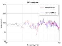
To add some concrete data to the discussion about the port placement and the "250 Hz issue" from post 740 I made a dirty experiment: I shortened the existing front/slot port to 22cm (cross section was not changed). While this results in a much higher bass-reflex tuning, the "250 Hz issue" is also (almost) gone; just compare the attachment with post post 740. It really does seem that the "250 Hz" issue was a resonance within the (long!) port.
The good news is that the 250 Hz issue can be avoided with a shorter front/slot port. The tuning frequency could be adjusted using a smaller cross section. However, the leakage of upper bass / lower midrange from the enclosure inside through the port is still a bit of a problem with the slot port below the woofer. The Monkey Coffin does sound cleaner with the rear port.
The good news is that the 250 Hz issue can be avoided with a shorter front/slot port. The tuning frequency could be adjusted using a smaller cross section. However, the leakage of upper bass / lower midrange from the enclosure inside through the port is still a bit of a problem with the slot port below the woofer. The Monkey Coffin does sound cleaner with the rear port.
Attachments
I am not arguing against the fact that: A decent implementation of a rear tubed port, is better than a sub optimal implementation of a slot port on the front.
I am also, not arguing against the fact that: The slot port placement in the box, in relation to driver placement, causes a resonance. The resonance does not change much in frequency, between a long and short slot port, in that specific location, but the affected area is in a slightly narrower bandwidth with a short port.
All the simulation data agrees with this, but it is not the port itself that causes the resonance.
It is the port, in relation to the box dimensions and driver placement.
I have tried pushing the port around a little bit, and the resonances are much less excited, and also pushed higher up in the frequency range, if you put the port throat around the middle of the enclosure. The port mouth can be anywhere you like, but the port throat should be around the middle rear or near the top rear internally.
The rear port will also very likely benefit from this, and perhaps one should consider shortening the rear port a bit and put a bend on it. At least if you absolutely must have a rear port.
The good news is that the 250 Hz issue can be avoided with a shorter front/slot port. The tuning frequency could be adjusted using a smaller cross section. However, the leakage of upper bass / lower midrange from the enclosure inside through the port is still a bit of a problem with the slot port below the woofer. The Monkey Coffin does sound cleaner with the rear port.
Did you also tried to split the port in several parts by placing vertical bracings in the port? Maybe the resonance is also cancelled that way.
I didn't follow all the last port discussions in detail, maybe I have missed such proposal already...
That was my original proposal, but the resonance will still be there.
I think I am seeing something on the reat port as well, which is why I suggested bending the port to change location of the port throat.
I think I am seeing something on the reat port as well, which is why I suggested bending the port to change location of the port throat.
Did you also tried to split the port in several parts by placing vertical bracings in the port? Maybe the resonance is also cancelled that way.
I didn't follow all the last port discussions in detail, maybe I have missed such proposal already...
I did not try this because the experiments showed that the resonance is determined by the length of the port. Adding braces along the length would be like using several ports of the same length, but smaller diameters. Since these port would be the same length, the resonance would be the same.
I did some more long days in the workshop, with the Monkey Coffin playing music. I tried again the different bass reflex ports (as described earlier), and also some tweaks to the DSP filters.
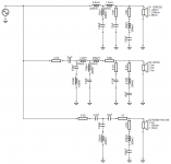
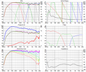
I attached my revised xover design (EL20190302) and the corresponding Vituix curves. Let me know what you think.
In particular, do you see any reason why I should not go ahead and buy the xover parts to build this (using the leftover money from the fundraising campaign)?
- I still prefer the rear port (Monacor BR-100HP, 140 mm long, centered on the rear of the enclosure). I'll leave it there. Tuning frequency is about 37 Hz (from the impedance curve, I still need to do the proper measurement by finding the excursion minimum of the woofer). Using a different port/tuning (different lengths, or front/slot port) is always a possibility. The good thing is that changing the bass reflex tuning hardly changes the upper impedance peak, so the the compensation of this peak in the x-over circuit is not affected. This meas builders can easily experiment with the port/tuning to suit their taste.
- The DSP filters I tried were the "Conventional 3B" and the "Elliptic 3.4mix" as described in post 685. Just to be sure, I measured the miniDSP filter curves from Pauls biquad coefficients, and they were extremely close to the filter transfer curves of the passive filters modelled in VituixCAD. As already mentioned earlier, the overall tonal balance is essentially the same for both filter designs. However, the Elliptic version is more "transparent" (it's a bit like using a better amplifier), so I stayed with the Elliptic version for the further testing.
- I made a few anechoic SPL measurements of the Monkey Coffin with the DSP filters in place, and I found very good consistency with the Vituix calculations (both individual drivers and summed response). This is not surprising since the Vituix output is just the "multiplication" of the unfiltered SPL curves and the filter transfer functions, but it's still good to confirm that the Vituix output is good.
- Listening tests showed that the overall balance was a tad too bright, a bit too much energy in the treble. This was fixed easily by reducing the tweeter level by 1.5 to 2 dB. A tiny bit of attenuation of the midrange might also be good (0.5 dB or so), but maybe that's just the acoustics of my workshop. Implementing these changes in the passive filters seems to be a piece of cake, as it can be done by simple changes of the series resistors.
I attached my revised xover design (EL20190302) and the corresponding Vituix curves. Let me know what you think.
In particular, do you see any reason why I should not go ahead and buy the xover parts to build this (using the leftover money from the fundraising campaign)?
Attachments
Last edited:
I did not try this because the experiments showed that the resonance is determined by the length of the port. Adding braces along the length would be like using several ports of the same length, but smaller diameters. Since these port would be the same length, the resonance would be the same.
Sorry, still have to post on the topic since your conclusion seems to be wrong 😉
I think its not the port length, which would have its own resonance, lowest resonant wavelength is at 2 * length of the port. 22cm long port =~ 780Hz. Resonances of open air columns
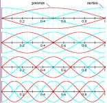
The box height is the only dimension which would result a standing wave at ~250Hz. Port being at the pressure node of such resonance at the enclosure end makes the resonance sound come through the port, it seems.
If it is so that a pressure node of a standing wave likes to come through the port, best place for a port would be in the middle of the enclosure (for the lowest standing wave in mind) where there is a velocity node (pressure antinode). See attachment for pressure nodes, red line 🙂
But, then the port is in the pressure node of the second harmonic at ~500Hz and that would leak through the port as much. If one wants to balance the attenuation between the "leaking" standing waves, best place for the port would be somewhere between 1/5 - 1/3 of the enclosure height which doesn't hit a pressure node of the worst offending (height related) standing waves. Maybe the two lowest resonances are the most troublesome, so hit 1/4 to attenuate first and second standing wave. Higher harmonics are attenuated more by the box lining at the top / bottom so maybe not a problem.
Alright, I'm out 🙂
Attachments
Last edited:
I think its not the port length, which would have its own resonance, lowest resonant wavelength is at 2 * length of the port. 22cm long port =~ 780Hz.
That's the "classical" bass reflex port resonance. However, it seem the original slot port we used in the Monkey Coffin had a 1/4 resonance, possibly because its one end was semi-terminated by the rear wall of the enclosure creating a pressure node. The resonance went away once I made the slot port shorter, moving the port throat further away from the enclosure rear wall. This shows that the issue was not due to a standing wave within the enclosure, which I did not change at all. Please take a look at the earlier posts with the measurements illustrating all this.
Last edited:
The resonance went away once I made the slot port shorter
No, Matthias. It did not go away.
The affected area is in a shorter pass band, but the resonance is still there, centered around the exact same frequency, just slightly less visible on the SPL measurement.
I have mentioned this before, I even mentioned the resonance would be there before you started building the box, asking if there was somewhere else you could put the port.
It seems like you are very interested in crossovers and baffle diffraction, but completely ignore what is going on inside the box.
***RANT ON***
Yes, the standing wave in the box is always there, no matter how long the slot port is. But that was never the problem, and dampening materials took care of most of those internal standing waves.
The problem is/was a resonance that showed up in the measurements with the long slot port, but did not show up in the short slot port. Also, this resonance did not change when I added damping material in the enclosure. The frequency of the resonance was exactly consistent with a 1/4 length resonance of the port. It did not fit the internal dimensions of the enclosure. Just take a look at my earlier measurements that demonstrate these points.
I measured the port options, and I listened to them. I know what works best for me, and I am not going back to this ad-nauseam discussion. If anyone wants to build the Monkey Coffin with a different port, feel free to do so.
The (small!) tweaks in the xover have much larger effects on the overall sound coming from the Monkey Coffin than the different bass reflex ports anyway. So can we please go back to the xover?
***RANT OFF***
Does anyone have any comments regarding the latest xover design?
You know, it seems you're contradicting yourself a bit on that last post. maybe you should edit that a little bit.
Anyway, keep having fun.
Wish you all the best.
I'm out too. 🙂
Anyway, keep having fun.
Wish you all the best.
I'm out too. 🙂
...Does anyone have any comments regarding the latest xover design?
...
 .......😛...
Last edited:
Technically, schematics and plots do look ok. Elliptical filters tend to sound bright. In my speaker with elliptical filtering the overall SPL is flat, but I have different drivers. With the Volt 3 inch midrange you have more power than a 7 inch midrange as used in my speaker for example.I attached my revised xover design (EL20190302) and the corresponding Vituix curves. Let me know what you think.
In particular, do you see any reason why I should not go ahead and buy the xover parts to build this (using the leftover money from the fundraising campaign)?
Applying steep filtering, like the ellipticals are, also implies more high frequency power for the same SPL curve. That is because the tweeter can push more power in space, because of a more high Q filtering with less overlap between the drivers.
Remark that changing resistors in the xo to adapt levels, also affects the curve shape (and sound), because the resistive load on the filter does change. In that way it is more recommended to use L-pads (if possible).
I did simulate the Monacor BR-100HP in Leap for the Monkey Box. fB is 37.7 Hz, that is close to the measurement and the same value as before with the front slot port.
The port area of 69 cm2 is on the limit to avoid port noise at maximum excursion. Calculating the minimum requirement of the port area conform R.Small gives 100 cm2 for xmax = 7 mm. So it is safe up to about 70 % of xmax, that looks ok.
And finally …. Leap simulates a port resonance of 850 Hz for this port size… without comments 🙂.
- Home
- Loudspeakers
- Multi-Way
- Open Source Monkey Box