Oh no, yet another faceplant moment... after another coffee it's been dawning at me that I once had (still have?) an MSc in physics+math (and a PhD that was remotely connected, but it's all long gone). Now you all know how meaningless these titles can be. Anyway, I looked up the high-school calculus of how to integrate over the surface of a sphere, and voila: the sin(theta) term is a simple calculus thing that's required for the angular integration steps over the surface of the sphere, see here. The sin(theta) term is not a weighting of the SPL. There is no weighting involved in the summation of the SPL over the sphere. So the power response really is the summed power radiated over the sphere, as explained by Paul. Simple.
Yep, I should have had that coffee before I looked at the Tykla paper. But just to rub it in: the sin(theta) term is not a weighting factor for the SPL! It is not related to the SPL or any other acoustic property or effect. It's just a calculus thing required for the integration over the surface of a sphere.
Well, if theta is the horizontal angle, then that's an awkward statement. If you mean that there should also be a sin(phi) term (where phi is the vertical angle as shown https://seos-project.eu/laser-rs/images/solid-angle-1.png), then that statement is wrong.
Looking at the Vituix manual, the information about the power response is a bit thin (page 26). What is the formula for the power response as used in Vituix? What is theta_n (I am assuming it's the horizontal angle)? What is Q(f) (I don't think it's the power response)? Where is the summation over the vertical angle? Is the spherical summation interval missing in the sum of Q(f)=...? It would be interesting to see the code, but since Vituix CAD is closed source I guess that's not possilble.
This seems like you are saying "it's good enough" simply because others have done it that way. How do you know it really is good enough? And what does "good enough" mean? Does it mean that the dual-plane method usually is within 0.1 dB of the full-sphere analysis? Or within 1 dB? Or within 10 dB? Saying it's "good enough" needs a bit more meat on the bone.
Sure. But you need to understand what you're following. I trust that was the case when you implemented the dual-plane method in Vituix, and that's why I was hoping you could provide some quantitative information/comparison regarding this issue.
I still think that a modeling tool (Leap?) might be useful to compare a complete full-sphere calculation of the power response with simplified calculations like the dual-plane approach or neglecting the rear sector. While this would not be based on real-world measurement data (which we won't be able to get for the full-sphere approach), it would still provide some quantitative information about how good or bad the simplified approaches really are.
This power-response discussion is interesting, but it is getting a bit off-topic. It might be useful to start a dedicated thread about this (feel free if you want to). I'll have another coffee and think about the next steps for the Monkey Coffin.
To understand the weighting, you have to read chapter 4 of Tylka very attentive.
sin(theta) weighting converts radial measurements in plane(s) to total radiated power on spherical surface i.e. to compatible with multiple measurements all around the speaker. I guess Tylka paper includes graphical explanation why sin(theta) is needed for that.
Yep, I should have had that coffee before I looked at the Tykla paper. But just to rub it in: the sin(theta) term is not a weighting factor for the SPL! It is not related to the SPL or any other acoustic property or effect. It's just a calculus thing required for the integration over the surface of a sphere.
sin(theta) weighting is needed for all planes - not just for horizontal.
Well, if theta is the horizontal angle, then that's an awkward statement. If you mean that there should also be a sin(phi) term (where phi is the vertical angle as shown https://seos-project.eu/laser-rs/images/solid-angle-1.png), then that statement is wrong.
Looking at the Vituix manual, the information about the power response is a bit thin (page 26). What is the formula for the power response as used in Vituix? What is theta_n (I am assuming it's the horizontal angle)? What is Q(f) (I don't think it's the power response)? Where is the summation over the vertical angle? Is the spherical summation interval missing in the sum of Q(f)=...? It would be interesting to see the code, but since Vituix CAD is closed source I guess that's not possilble.
This is practical method especially for diy ... Measurement in few planes (with constant angle step) is easy, fast and mechanically compact. ... We know that it's not fully accurate ... But it's good enough method for textbooks ... We have quite good reason to trust that it's also good enough for diy. I would say it's state of the art in diy-scene and better to take advantage of it.
This seems like you are saying "it's good enough" simply because others have done it that way. How do you know it really is good enough? And what does "good enough" mean? Does it mean that the dual-plane method usually is within 0.1 dB of the full-sphere analysis? Or within 1 dB? Or within 10 dB? Saying it's "good enough" needs a bit more meat on the bone.
This depends on what point "understanding" is reached. Before that moment it's better to follow than violate if you are forced to do some actions in early phase.
Sure. But you need to understand what you're following. I trust that was the case when you implemented the dual-plane method in Vituix, and that's why I was hoping you could provide some quantitative information/comparison regarding this issue.
I still think that a modeling tool (Leap?) might be useful to compare a complete full-sphere calculation of the power response with simplified calculations like the dual-plane approach or neglecting the rear sector. While this would not be based on real-world measurement data (which we won't be able to get for the full-sphere approach), it would still provide some quantitative information about how good or bad the simplified approaches really are.
This power-response discussion is interesting, but it is getting a bit off-topic. It might be useful to start a dedicated thread about this (feel free if you want to). I'll have another coffee and think about the next steps for the Monkey Coffin.
YepBut just to rub it in: the sin(theta) term is not a weighting factor for the SPL! It is not related to the SPL or any other acoustic property or effect. It's just a calculus thing required for the integration over the surface of a sphere.
No need for me at this moment, maybe better to focus on the Monkey Box and do the needed investigation for a good understanding of all for the project.This power-response discussion is interesting, but it is getting a bit off-topic. It might be useful to start a dedicated thread about this (feel free if you want to). I'll have another coffee and think about the next steps for the Monkey Coffin.
Agree 100%, therefore my question to Kimmosto in post 860, to add such function in VCAD.I still think that a modeling tool (Leap?) might be useful to compare a complete full-sphere calculation of the power response with simplified calculations like the dual-plane approach or neglecting the rear sector. While this would not be based on real-world measurement data (which we won't be able to get for the full-sphere approach), it would still provide some quantitative information about how good or bad the simplified approaches really are.
I will look what I can do in Leap concerning off axis measurements in not complete horizontal and vertical orbits, like done now for the Monkey Box.
Last edited:
if theta is the horizontal angle, then that's an awkward statement. If you mean that there should also be a sin(phi) term ..., then that statement is wrong.
Any Greek letter is fine. It's just sin(off-axis angle). Result of radial dual plane is average of horizontal and vertical powers.
It's just sin(off-axis angle). Result of radial dual plane is average of horizontal and vertical powers.
The greek alphabet is not relevant here. The coordinate system is. Just make sure that the sine(...) term exists only once (for the horizontal angle, but not for the vertical angle).
Can you provide the formula of how Vituix calculates the power response? I would like to understand what I am looking at in the diagram of my Vituix project of the Monkey Coffin.
Just make sure that the sine(...) term exists only once (for the horizontal angle, but not for the vertical angle).
Horizontal and vertical are separate sequences i.e. response groups so there's only one sin() function at a time. Total is average of those two - as wrote few minutes ago. Calculation goes to woods if sin() is not used for vertical plane at all. We would get different result by just imaging that normal orientation is rotated 90 deg right/left. It's obvious that power response does not change a bit by human decision.
I would like to understand what I am looking at in the diagram of my Vituix project
You can validate power & DI calculation for example with:
* Ideal directivity data created with Enclosure tool of version 1.1
* Directivity export of Diffraction tool
* Manually created off-axis response files.
Basic test is to create ideal omni, cardioid and dipole responses to 0-180 deg, with or without cone directivity. Then monitor directivity and power & DI charts.
Switch half space on/off in Options window to see the effect.
Horizontal and vertical are separate sequences i.e. response groups so there's only one sin() function at a time. Total is average of those two...
This confuses the hell out of me. Take a look at equations (1) or (3) in the Tylka paper. The summation is done over the entire sphere, both angles are integrated / summed in one go. I don't understand your "separate sequence" statement. Also note that there is no sin(phi) term in equation (1). Also, omega_n in equation (3) does not depend on m, so it depends on the horizontal angle only, not on the vertical angle.
PLEASE show the formula used in Vituix CAD so that I can understand how power response is calculated in Vituix.
You can validate power & DI calculation for example with:
* Ideal directivity data created with Enclosure tool of version 1.1
* Directivity export of Diffraction tool
* Manually created off-axis response files.
Basic test is to create ideal omni, cardioid and dipole responses to 0-180 deg, with or without cone directivity. Then monitor directivity and power & DI charts.
Switch half space on/off in Options window to see the effect.
That's a good idea, thanks! I will look into this later!
Matthias,
can you tell me where to find the last off axis measurements of all the drivers in the Monkey Box, used for your VCAD simulations.
I am working out something in Leap.
Thanks.
can you tell me where to find the last off axis measurements of all the drivers in the Monkey Box, used for your VCAD simulations.
I am working out something in Leap.
Thanks.
Matthias,
can you tell me where to find the last off axis measurements of all the drivers in the Monkey Box, used for your VCAD simulations.
I am working out something in Leap.
Thanks.
Post 576.
This confuses the hell out of me... PLEASE show the formula
Whole angle listing, weighting, directivity calculation and visualization package is too big and fragmented mess to explain anything for anybody - including myself 🙂 Effect would be probably quite opposite with dozens of new questions I really don't have time and motivation to answer. Very sorry.
Think this as measurement sequence. Assume that angle step is some constant.
First you measure horizontal plane 0-180 deg. Conversion factors with sin 0...90...180 deg are 0...1...0. Vertical plane is constant 0 deg whole time so that part is null.
Then you measure vertical plane 0-180 deg. Conversion factors with sin 0...90...180 deg are 0...1...0. Horizontal plane is constant 0 deg so that part is null here.
Conclusion: one sine operation is active at a time.
Power of each measurement point is pressure^2. Those are summed and divided by total number of measurements hor+ver. There you have result proportional to total radiated power. It is just an average of two planes - kinda result to diagonal plane to 45 deg.
This calculation system enables measuring along additional diagonal orbits - as many as you like to get more and more points and accuracy to result. So "angle" in sin(angle) conversion factor is not necessarily exact vertical or horizontal. It is just "off-axis angle" in 3D coordinate system.
Happy now? This is quite easy to demonstrate with directivity exports by Enclosure tool 1.1. I just checked with ideal cardioid and dipole that calculation gives correct result no matter is horizontal, vertical or both planes enabled in Options window.
Whole angle listing, weighting, directivity calculation and visualization package is too big and fragmented mess to explain anything for anybody - including myself 🙂 Effect would be probably quite opposite with dozens of new questions I really don't have time and motivation to answer. Very sorry.
Well, the formula used to calculate the curves in Vituix CAD should be in the manual. No excuses here. Otherwise users don't know what they are looking at. If the developer of a software package can't give the formula of how his code calculates things, I am not sure I want to trust the results of this software.
Think this as measurement sequence. ... So "angle" in sin(angle) conversion factor is not necessarily exact vertical or horizontal. It is just "off-axis angle" in 3D coordinate system.
I am sorry, but this seems to be wrong. This is not how the calculation of the power response works!
The correct procedure would be something like this:
- The first set of measurements gives you the SPL responses at different horizontal angles theta, and vertical angle phi=zero.
- The second set of measurements gives the SPL responses theta=0 and different vertical angles phi.
- You plug in the data from both sets of measurements into the denominator of equation (1) in the Tylka paper (or equation (3)).
I am not sure I want to trust the results of this software.
Already told twice how you can verify that. Some math hieroglyphs in manual cannot prove the result any better. But of course some knowlegde about DI and power is needed to evaluate it.
Take it or leave it. Your choice.
Some curves to think about. We can discuss about later on.
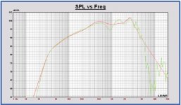
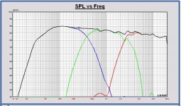
SPL on axis curves for each driver:
- SPL on axis of measurement (green) and Leap simulation (red)
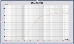
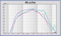
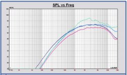
Power curves for each driver:
- Measured power in the single horizontal half plane conform Tylka (green)
- Leap single horizontal half plane power (blue) and full sphere power (red) conform Tylka
- Leap radiated power per driver (dark blue)
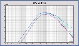
Power curve with last EL34 X-over, using measured driver powers
Remarks:
- No tweeter waveguide in Leap, simple driver models without any SPL correction
- Measured SPL curves, +1.5 dB added to match with Leap
- Power conform Tylka is expressed as the SPL of a point source in full space with the same power.
- Power in Leap radiated by the driver is expressed as the SPL of a point source on infinite baffle with the same power.
SPL on axis curves for each driver:
- SPL on axis of measurement (green) and Leap simulation (red)
Power curves for each driver:
- Measured power in the single horizontal half plane conform Tylka (green)
- Leap single horizontal half plane power (blue) and full sphere power (red) conform Tylka
- Leap radiated power per driver (dark blue)
Power curve with last EL34 X-over, using measured driver powers
Remarks:
- No tweeter waveguide in Leap, simple driver models without any SPL correction
- Measured SPL curves, +1.5 dB added to match with Leap
- Power conform Tylka is expressed as the SPL of a point source in full space with the same power.
- Power in Leap radiated by the driver is expressed as the SPL of a point source on infinite baffle with the same power.
Attachments
-
 MonkeyB SPL on axis curves woofer.JPG61.6 KB · Views: 747
 -
 MonkeyB SPL on axis curves midrange.JPG62.3 KB · Views: 748
 -
 MonkeyB SPL on axis curves tweeter.JPG61.1 KB · Views: 745
 -
 MonkeyB power curves woofer.JPG66 KB · Views: 742
 -
 MonkeyB power curves midrange.JPG64.6 KB · Views: 746
 -
 MonkeyB power curves tweeter.JPG65.2 KB · Views: 159
 -
 MonkeyB Power curves with X-over.JPG149.9 KB · Views: 191
Last edited:
Some comments on the power curves.
- As expected, measuring only off axis SPL in a single half plane, the resulting power response is representative for the full sphere power only in the frequency region where the speaker is omnidirectional. For frequencies above the bafflestep, where the speaker becomes unidirectional, the single half plane power becomes higher than the full sphere power.
- The single half plane power calculated with the measurements maps on the Leap single half plane power simulation for the woofer, for the midrange expect around the bafflestep frequency, but not for the tweeter because of the waveguide.
- As not expected (by me 🙂 ), the single half plane power of the tweeter with waveguide is higher than the tweeter without waveguide. In full sphere it is not measured yet, but it is to be expected that the behavior is the same, that the power becomes also higher in full sphere using a waveguide.
- Interpreting the power sum with X-over, this is a single half plane power curve. The full sphere power will be lower for frequencies above the bafflestep frequency.
- Maybe interesting also to compare the results with VCAD?
Last edited:
Measured power ... conform Tylka
I am not quite sure how to interpret this since I have no clue about the features available in LEAP. Did you implement the Tylka equation in LEAP? Or did use the existing tools in LEAP to calculate power response that should be consistent with the Tylka approach (integration over a sphere around the speaker)?
Leap radiated power per driver (dark blue)
That's based on the concept of calculating the power output from the driver (using the TSP etc.), correct?
As expected, measuring only off axis SPL in a single half plane, the resulting power response is representative for the full sphere power only in the frequency region where the speaker is omnidirectional. For frequencies above the bafflestep, where the speaker becomes unidirectional, the single half plane power becomes higher than the full sphere power.
I can see why one would expect this. However, my quick-n-dirty experiments using synthetic data in VCAD showed that the shape/slope of the power response was hardly affected by neglecting the rear hemisphere. The major difference between the full-sphere and half-sphere calculation was the the absolute level of the power response changed a bit. I'll look into this a bit more.
As not expected (by me 🙂 ), the single half plane power of the tweeter with waveguide is higher than the tweeter without waveguide.
Is this because the waveguide improves the coupling of the tweeter to the air, allowing the tweeter to transfer more power to the air?
Maybe interesting also to compare the results with VCAD?
Yes, I will play with this a bit in the next few days. I have also implemented the Tylka equation to calculate the power response from ASCII data files in GNU Octave. It's here, and it gives slightly different results than VCAD (see here). I don't know yet why this is.
Overall, I still wonder how important it is to get full-sphere measurements in order to make progress with the Monkey Coffin. Yes, a proper assessment of the power response would require the full-sphere measurements. However, I don't want to become excessively obsessed with the power response assessment for the Monkey Coffin. Do we absolutely need better power response than what we have? We already know the power response is quite linear with a slight slope, with no nasty bumps, dips, or other undesired features. In case we do need a better assessment of the power response, do we need it now, or can we do it later?
I am asking these things because my workshop is currently cramped with other things that have higher priority than the Monkey Coffin (yes... but we need a new door for our house!), and there is currently simply space to do proper acoustic measurements. In addition, I wanted to build a second box to see how a stereo pair would sound in my listening rooms.
What does everyone think? Build a stereo pair first? Work out the power response properly first? Try the augerpro waveguides first? Something else?
Leap has a curve averaging tool inclusive weighting etc. to calculate the power conform the Tylka formula.
Driver power output is calculated with TSP, radiation impedance , etc…yes.
A waveguide does change the radiation impedance seen by the tweeter and thus also its radiated power. I have to look how to simulate waveguide behavior for the future, in Leap it isn’t possible.
I think it is best to make a stereo setup as the next step. Maybe it will give another meaning about the sound and some extra tuning is needed. At that time the power curve is useful to have. With the frontal measurements you already have a good view on the power, the transition between the drivers etc. No need for full sphere measurements at this moment.
In my last speaker design, I used the power response for tuning. With a flat power from the bafflestep frequency up to 8 kHz, the sound was the best (for that speaker). You have to look to power, more and more convinced about that.
I think it's best to make a stereo setup as the next step because Mr. mbrennwa deserves to listen to a system with these speakers after over 6 months working on the design with all your help!
I saw the first posts for this project, a combination of sound performance and what we dream of as a speaker, including even some visual things that just "look right", but I never subscribed because threads like this often never get anywhere. But this one still has the cool stuff that rings the bells of what I've always felt somehow was a serious speaker:
-3 way
-A 2ish cu. ft. box- room for up to a medium sized monkey
-A clone of the ATC dome midrange that I've only heard good about, designed by a speaker company I've never heard bad about, loved by both recording engineers and Lynn Olsen!
-a 12" bass driver, because 12" is RIGHT!
-Highish efficiency because I do feel they tend to sound "lively"
-Designed to work well with the ACA amp- Ok, we sell the ACA kit in the diyAudio Store, so I really liked this! And I already have quite a few ACAs around since I produce the kits. Recently we've increased the power supply to a 24v model sourced from Meanwell which increases the output to a solid 7 watts rather than barely 6 watts, and with a lower noise floor. Also the chassis' are now 2 channel, and a few simple wiring changes allow use of both channels together as a monoblock in a bridged, paralleled, or balanced configuration (with the included XLR socket) This can give 15wpc or allow driving much lower impedance loads.
So I'm pretty convinced this is the speaker for me once you work out these final issues, and I can't wait because I know you will. While the bookshelf idea was a nice idea, I think the sound quality will be so good that they will mostly be used with the front baffle at least a meter from the wall. There are too many compromises required to make a "bookshelf speaker" that actually works on a shelf and also works a bit away from a wall.
I found the FaitalPRO 12PR320 in the USA at $238 from Usspeaker. Parts Express sells the Faitalpro line but not that speaker driver. I'm pretty confident that they would special order if people wanted them, and their commercial account prices are usually a great deal!
Mark
Last edited:
Thank you Mark for bringing back the focus of what we're trying to do here! Sometimes it's useful to have people not following each and every post, so they can still see the big picture after a few months.
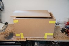
Here's how far I got with the second prototype for now. Building another quick'n'dirty monkey coffin, and some beautiful augerpro waveguides that fit the Scan R2904 like a glove!
I will be away for a few weeks, so don't hold your breath for more progress with this.
I will be away for a few weeks, so don't hold your breath for more progress with this.
Attachments

- Home
- Loudspeakers
- Multi-Way
- Open Source Monkey Box