...into the JBL Ewave WG...
That's a pretty long horn, so I'd expect issues with time alignment relative to the mid.
I have sent an R2904 to augerpro (the guy behind the Open Source Waveguides for 3D printing). He agreed to design a waveguide for us, so let's see what he comes up with.
In the meantime I'd like to play around a bit further with the tweeter on the Monkey Coffin prototype baffle. I'd also like to take a look a the time alignment between the mid and tweeter. I can think of many ways to measure the time offset, but I am sure others have more experience with this. What is a simple and effective method?
I compare the impulse starting time of a mls measurement for both drivers.
Both drivers mounted on IEC baffle, flush with baffle and the microphone at same position on axis.
I use a Clio system of 2007, the sample frequency is 48 kHz, so the accuracy is only +/- 7mm. I don't know how to do it better at this time.
This method is not possible with some measurement tools.
Both drivers mounted on IEC baffle, flush with baffle and the microphone at same position on axis.
I use a Clio system of 2007, the sample frequency is 48 kHz, so the accuracy is only +/- 7mm. I don't know how to do it better at this time.
This method is not possible with some measurement tools.
It's the shortest flare I own. But I forgot you guys are going down the llo-po passive road.That's a pretty long horn, so I'd expect issues with time alignment relative to the mid.
I compare the impulse starting time of a mls measurement for both drivers.
Both drivers mounted on IEC baffle, flush with baffle and the microphone at same position on axis.
I use a Clio system of 2007, the sample frequency is 48 kHz, so the accuracy is only +/- 7mm. I don't know how to do it better at this time.
This method is not possible with some measurement tools.
So you measure first the tweeter impulse and then the mid impulse in separate measurements? That result will depend on the repeatability of the timing in the audio processing. I'll check...
I was thinking more about measuring the summed anechoic response of both drivers simultaneously, and moving the microphone vertically, or tilting the baffle. Could also do this by reversing the polarity of one driver to confirm relative phase.
Oh, and I don't have an IEC baffle. Would you agree that this should also work on the Monkey Coffin baffle?
Assume we get the time alignment perfectly right without x-over, what will we get once the x-over is in place? Will the x-over mess up the time alignment?
In the Clio the repeatability is ok, but I do every measurement several times to be consistent. You have to check that yes.
You can do the measurement in the Monkey Coffin baffle. You have to set the microphone distance from baffle accurately the same for each driver on its axis. That is the reason I use the IEC baffle, the center of both drivers is at the same place and I don’t have to move the microphone.
There is a difference between steady state phase response in the frequency domain and arrival time in the time domain. Of course they are related, a position shift backwards will give a phase lag, but steady state phase response is also related to the driver parameters and the X-over response.
It is possible to measure the acoustical center in steady state using minimum phase responses of the drivers, and add some delay to one of the drivers until the measured phase difference is the same as the minimum phase difference for both drivers. But that is in the assumption that both drivers have a minimum phase behavior. In the operating area of the driver it is minimum phase, but not always around the bandwidth frequency or close to break up.
Same remark with an without X-over, the steady state phase will be affected by the X-over of course, but at first the arrival time has to be the same for both drivers without X-over. Of course the X-over will affect the impulse shape, but not the start of the impulse.
Also acoustical center alignment is important to keep the arrival times the same off axis.
We can try this:
If you should do a SPL measurement of each driver in the baffle at exactly same distance from baffle on axis. And place the start of the FFT window at exact the same place to calculate the FFT for both.
I can do a minimum phase transform on the measured SPL and add some delay on the tweeter until the measured phase maps on the minimum phase. With the delay added the acoustical center difference can be calculated. I have never done this way, but we can try it.
I can do a minimum phase transform on the measured SPL and add some delay on the tweeter until the measured phase maps on the minimum phase. With the delay added the acoustical center difference can be calculated. I have never done this way, but we can try it.
Thanks for your comments, changing my mind to impulse travel time instead of continuous sine signals made things much clearer. If my measurement setup* gives repeatable time lags, I can just calculate the excess phase of the two drivers. The difference between these should give the time offset between the two. I'll take a look at this during the next few days. I hope I can squeeze in some workshop quality time 🙂
(*I would be surprised if my RTX6001 does not give consistent timing)
I checked acoustical center difference with an older Clio measurement of a tweeter and a 7 inch midrange.
Using the time difference between the impulse start times of both drivers, acoustical center difference is 28 mm.
Using the steady state minimum and measured phases, like I describe it in post 305, acoustical center difference is 33mm.
Knowing the resolution of my 48 kHz Clio system is only +/- 7 mm, this is a very good comparison result.
If you send me your SPL measurements later on, I can double check acoustical center also for you.
Last edited:
I have now measured the offset of the acoustic centres of the tweeter and the mid. As it turned out, my test setup is not great when it comes to the consistency of the time delay of the recorded test signals. It was therefore not possible to compare the relative time delays of the impulse responses of the tweeter and the mid.
The way out was to measure the tweeter and mid simultaneously in a single measurement in order to avoid the uncontrollable time delays between two separate tweeter/mid measurements. The procedure was as follows:
- Tweeter and mid were both mounted flush on the Monkey Coffin prototype baffle as shown on the photo.
- The "depth" of the tweeter (Scan R2904 in WG148) is 20mm (horizontal distance between baffle plane and the point where the voice coil meets the "dome"). The "depth" of the mid (Volt VM752) is 28mm.
- The microphone was mounted exactly 100cm away from the baffle, at the height of the center between the tweeter and the mid (horizontal line between tweeter and mid as seen on the photo). The distances between the microphone and the tweeter or mid are therefore the same.
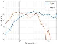
- The SPL responses of the tweeter and mid were measured separately to deterine the frequency band where both drivers have "flat" response (the "overlap frequency band").
- The tweeter and midrange were connected in parallel, with the tweeter reversed relative to the mid.
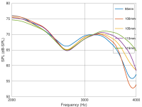
- The anechoic response of the tweeter + mid was measured repeatedly, with the microphone at different heights.
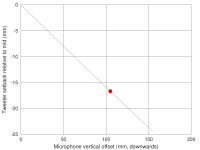
Moving the microphone vertically results in different microphone/tweeter and microphone/mid distances. Once the acoustic centres of the tweeter and the mid are perfectly aligned at a given microphone position, the reversed polarity of the tweeter and the mid results in a a dip of the SPL response in the "overlap frequency band". Then it's just a matter of Pythagoras to work out the difference between the mic/tweeter and mic/mid distances at this microphone position in order to determine the offset of the acoustic centres of the tweeter and the mid.
Results:
- The "overlap frequency band" is about 2-4 kHz.
- The strongest cancellation in this frequency band occurs with the microphone about 100-110mm below the center of the tweeter and mid.
- The tweeter would need to mg ove backwards by about 16 mm to achieve perfect time alignment.
16 mm is about 10% of the wavelength of the planned x-over frequency (2-2.5 kHz), so the current WG148/R2904/VM752 set up is not terribly bad. Is this good enough, or should we try to improve this further (with a deeper waveguide)?
The way out was to measure the tweeter and mid simultaneously in a single measurement in order to avoid the uncontrollable time delays between two separate tweeter/mid measurements. The procedure was as follows:
- Tweeter and mid were both mounted flush on the Monkey Coffin prototype baffle as shown on the photo.
- The "depth" of the tweeter (Scan R2904 in WG148) is 20mm (horizontal distance between baffle plane and the point where the voice coil meets the "dome"). The "depth" of the mid (Volt VM752) is 28mm.
- The microphone was mounted exactly 100cm away from the baffle, at the height of the center between the tweeter and the mid (horizontal line between tweeter and mid as seen on the photo). The distances between the microphone and the tweeter or mid are therefore the same.
- The SPL responses of the tweeter and mid were measured separately to deterine the frequency band where both drivers have "flat" response (the "overlap frequency band").
- The tweeter and midrange were connected in parallel, with the tweeter reversed relative to the mid.
- The anechoic response of the tweeter + mid was measured repeatedly, with the microphone at different heights.
Moving the microphone vertically results in different microphone/tweeter and microphone/mid distances. Once the acoustic centres of the tweeter and the mid are perfectly aligned at a given microphone position, the reversed polarity of the tweeter and the mid results in a a dip of the SPL response in the "overlap frequency band". Then it's just a matter of Pythagoras to work out the difference between the mic/tweeter and mic/mid distances at this microphone position in order to determine the offset of the acoustic centres of the tweeter and the mid.
Results:
- The "overlap frequency band" is about 2-4 kHz.
- The strongest cancellation in this frequency band occurs with the microphone about 100-110mm below the center of the tweeter and mid.
- The tweeter would need to mg ove backwards by about 16 mm to achieve perfect time alignment.
16 mm is about 10% of the wavelength of the planned x-over frequency (2-2.5 kHz), so the current WG148/R2904/VM752 set up is not terribly bad. Is this good enough, or should we try to improve this further (with a deeper waveguide)?
Attachments

Last edited:
Midrange response looks quite difficult, but the dip at 2,2khz gets compensated off-axis.
this measurement was here earlier
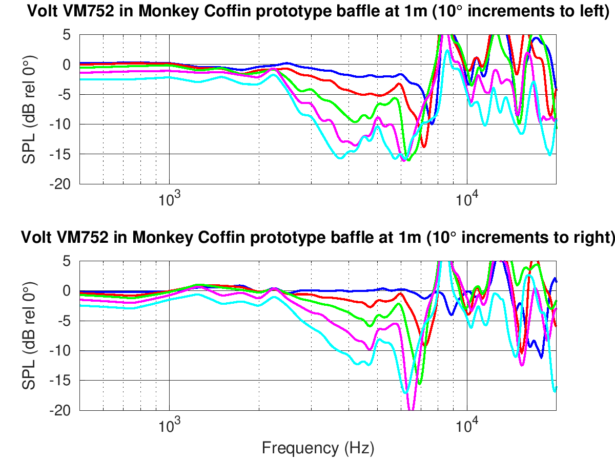
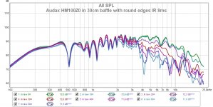
This is a shallow cone 4" Audax HM100Z for comparison, 0-60¤. Same phenomenom at 3,4kHz.
this measurement was here earlier
This is a shallow cone 4" Audax HM100Z for comparison, 0-60¤. Same phenomenom at 3,4kHz.
Attachments
Last edited:
This is why I use dual channel measurements! If the frequency response is not flat and smooth, neither will the phase be, so a null can arise from that, which is not necessarily due to AC offset alone. Also, the electrical filter also causes phase shift, but it won't be equal for both drivers for the simple reason that both drivers don't have the same (mirrored really) response, they will need different electrical filtering, again causing the null to move. It's all relative so what is "correct"? If you are forced to do it this way, I would take the measurements as you started with the mic centered, then actually model a crossover with HP and LP such that the driver responses match an LR4 or LR2 target response - just amplitude, don't worry about phase integration. Then flip the polarity to whatever would produce a null, and start adding Z to the driver until you produce a deep null. Use that wavelength as your AC offset.
Just my .02, I could be wrong. But for 10 years I've watched people use different methods to wrestle with this issue because of exactly the complications I've listed. The AC is only apparent and relative. I just use dual channel and be done with it. What software do you use?
Just my .02, I could be wrong. But for 10 years I've watched people use different methods to wrestle with this issue because of exactly the complications I've listed. The AC is only apparent and relative. I just use dual channel and be done with it. What software do you use?
I just use dual channel and be done with it. What software do you use?
Dual channel = two microphones? How do you set this up?
I use MATAA. It's not easy, but very flexible.
the dip at 2,2khz gets compensated off-axis.
this measurement was here earlier
Baffle edge diffraction.
This is a shallow cone 4" Audax HM100Z for comparison, 0-60¤. Same phenomenom at 3,4kHz.
Baffle edge diffraction?
Dual channel means one soundcard channel is the mic, and the other takes a signal off the speaker wire. This signal is used as "Time 0", and the mic signal is referenced to that. Since all measurements have the same absolute start time (Time 0) the AC or delay can be measured directly.
Soundeasy does this, I think VituixCad does too.
Soundeasy does this, I think VituixCad does too.
Dual channel means one soundcard channel is the mic, and the other takes a signal off the speaker wire.
Ah, loopback. Of course! That should fix the issue! Silly me...
I had a loopback option in MATAA a long time ago to compensate for the poor frequency response of the soundcard I had back then. The functionality is still in the code, but I haven't used it for a long time. I will check if it still works...
EDIT: the above method also inherently imbeds the AC offset into the phase of the drivers, so there is no Z value to worry about, just measure and model.
Ah, loopback. Of course! That should fix the issue! Silly me...
I had a loopback option in MATAA a long time ago to compensate for the poor frequency response of the soundcard I had back then. The functionality is still in the code, but I haven't used it for a long time. I will check if it still works...
Basically yes. You can take that reference channel from a number of points, depending on what sources of "error" you want to remove. Right off the soundcard output is easy because it's just one RCA wire. But say for example the amp isn't exactly flat (common at the ends of the frequency response), that is where building a jig box to take the Ref signal from just prior to the driver itself is handy. All upstream sources of error are effectively removed from the driver response.
Matthias,
About your measurement procedure, it can work, but I think it has to be done as follows.
At first you have to know how much the reversed tweeter has to be moved backwards in an AC aligned condition for maximum cancellation.
At second you measure how much the reversed tweeter has to be moved backwards in the actual AC condition for maximum cancellation. That is what you have done now.
The difference between both offsets is the AC difference between the drivers.
At the AC the phase of the driver is minimum phase.
So if you calculate the minimum phase response of both drivers out of the SPL measurements, the first offset can be found. I have done that and the tweeter offset backwards is 17 mm
If you have measured 16 mm now in the actual condition, the acoustical center of the tweeter is only 1 mm in front of the AC of the midrange.
This is a complex way of measuring, also the minimum phase calculation has to be correct, but it is possible in this way.
Augerpro:
Of course your proposal is the most easy.
Also in the Clio, time = 0 is set in the mls impulse response measurement and you can get the offset immediately.
I would take the measurements as you started with the mic centered, then actually model a crossover with HP and LP such that the driver responses match an LR4 or LR2 target response - just amplitude, don't worry about phase integration. Then flip the polarity to whatever would produce a null, and start adding Z to the driver until you produce a deep null. Use that wavelength as your AC offset.
Hi Augerpro,
This is a way to realize the best phase aligning with X-over. Interesting with a digital filter, where AC offset can be changed. In an existing application with passive filter, the AC offset cannot be changed anymore or it is difficult to realize.
IMO, the best is to design an X-over on target as good as possible for amplitude AND phase for an existing AC offset condition.
Remark that higher order filters have also a non flat groupsdelay, where you have to live with and affects timing also.
Last edited:
Paul> probably some confusion on my part, so forgive me if I mangle your description. In your method there is an unspoken assumption that I believe must be true for it to work: both drivers have absolutely flat frequency and therefore phase response. But no drivers are like that. The variation from flat will contribute to cancellation, but not due to AC offset which will have its own separate contribution.
So you have to somehow remove that contribution from the natural frequency response variation so all that is left is AC offset. I suppose one could EQ the response to perfectly flat and then calculate AC offset by looking at how far apart the phase responses. But it is easy to simply model an LR type crossover and accomplish the same thing. Once the frequency response of each driver is (mostly) the ideal of that filter type, any other difference in phase between drivers must be due to flight time, i.e., AC offset. Once you tweak the driver Z to get good cancellation, you have also found the offset. Now you design with this value in mind and when you model the actual crossover, the result should be behave as whatever the filter type ideal is because you have physically aligned the AC correctly.
So you have to somehow remove that contribution from the natural frequency response variation so all that is left is AC offset. I suppose one could EQ the response to perfectly flat and then calculate AC offset by looking at how far apart the phase responses. But it is easy to simply model an LR type crossover and accomplish the same thing. Once the frequency response of each driver is (mostly) the ideal of that filter type, any other difference in phase between drivers must be due to flight time, i.e., AC offset. Once you tweak the driver Z to get good cancellation, you have also found the offset. Now you design with this value in mind and when you model the actual crossover, the result should be behave as whatever the filter type ideal is because you have physically aligned the AC correctly.
Last edited:
Baffle edge diffraction.
Baffle edge diffraction?
My baffle is 30cm wide with rounding radius 4cm, speaker in midline. Your test baffle looks narrower, and the dip is at same F left/right - doesn't match with baffle effect!
My guess is that the Volt's steep waveguide-like edges make it disperse like a 6" woofer. That dip is in factory datasheet too.
Last edited:
- Home
- Loudspeakers
- Multi-Way
- Open Source Monkey Box