Will the use of a waveguide also reduce the diffraction effects of the cabinet?
If front baffle is wider than waveguide and depending on crossover frequency it will reduce but not solve them. If the crossover frequency between wg tweeter and midrange is above roughly 2.5KHz the effects of diffraction will hit midrange the most. If lower (as i'd do it because of vertical distance between acoustic centers of midrange and tweeter) it will affect them both. So you will have diffraction patterns of two drivers together with asymetrical layout to deal with so you'd achieve flat power response. Too many variables that, if not treated, will diminish performance drivers are capable of.
Two separate boxes (one narrow for mid-tweet and other wider for woofer) would be better solution with less unknowns, less diffraction on midrange and tweeter and can be made "on a kitchen table".
Something like this:
Last edited:
Based on Matthias’ front baffle proposal, I did redraw the cabinet, see attached pdf.
Also looked to the basreflex system, internal volume and tuning frequency, F3, F6, minimum impedance with filter,…
Choosing the depth 42 cm, the internal netto volume available for the basreflex system is 77 L. Choosing 22 mm for cabinet walls now and also 22 mm for the top panel of the port. Not yet taken bracing into account.
I have following proposal (just to finalize some parameters for the prototype).
Basreflex system, driver = Faital 12PR320 Matthias measurement, VB = 75 L, FB = 35 Hz (port area = 162 cm2, port length = 31 cm).
Then F3 = 49.5 Hz and F6 = 35 Hz.
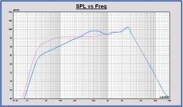
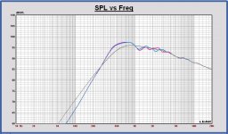
In first plot, Faital 12PR320 in cabinet, infinite baffle response in pink color, full space response in blue.
Adding X-over, the minimum impedance becomes 4.75 Ohm, first check (taken 0.2 Ohm for serial resistance of X-over coils).
Choosing for a more Butterworth B4 response, the minimum impedance will become lower.
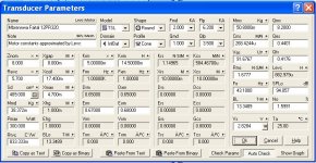
For Kaffimann: netto internal cabinet dimensions B x H x D = (32,4 x 61,5 x 37,6) cm; port area = 162 cm2, port length is 31 cm. TSP parameters of Matthias' Faital in attach.
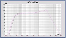
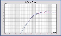
In second plot, the B4 version in grey color to compare with the proposal, both on infinite baffle.
A B4 version is tuned at 43 Hz, port length is 20 cm.
You can see the B4 has less low frequency extension (as Kaffimann told us already 1000 times 🙂)
Also looked to the basreflex system, internal volume and tuning frequency, F3, F6, minimum impedance with filter,…
Choosing the depth 42 cm, the internal netto volume available for the basreflex system is 77 L. Choosing 22 mm for cabinet walls now and also 22 mm for the top panel of the port. Not yet taken bracing into account.
I have following proposal (just to finalize some parameters for the prototype).
Basreflex system, driver = Faital 12PR320 Matthias measurement, VB = 75 L, FB = 35 Hz (port area = 162 cm2, port length = 31 cm).
Then F3 = 49.5 Hz and F6 = 35 Hz.
In first plot, Faital 12PR320 in cabinet, infinite baffle response in pink color, full space response in blue.
Adding X-over, the minimum impedance becomes 4.75 Ohm, first check (taken 0.2 Ohm for serial resistance of X-over coils).
Choosing for a more Butterworth B4 response, the minimum impedance will become lower.
For Kaffimann: netto internal cabinet dimensions B x H x D = (32,4 x 61,5 x 37,6) cm; port area = 162 cm2, port length is 31 cm. TSP parameters of Matthias' Faital in attach.
In second plot, the B4 version in grey color to compare with the proposal, both on infinite baffle.
A B4 version is tuned at 43 Hz, port length is 20 cm.
You can see the B4 has less low frequency extension (as Kaffimann told us already 1000 times 🙂)
Attachments
I haven't seen any measurements in this thread of midrange and tweeter mounted on a baffle with and without facetes. When properly implemented they work great.
That post may have been a while ago, maybe in one of the earlier Open Source Speaker threads. Just take a look at this (scroll down to see the data).
If boxy shape of cabinet is prefered, for whatever reason that may be, i'd make front baffle covered with felt or foam to reduce diffraction ...
How would the felt or foam affect diffraction at the baffle edges?
Will the use of a waveguide also reduce the diffraction effects of the cabinet?
Yes. The baffle edges get less "illuminated" due to the forward focusing of the sound field by waveguides (mid and tweeter), so the diffraction effects get less.
Two separate boxes (one narrow for mid-tweet and other wider for woofer) would be better solution with less unknowns, less diffraction on midrange and tweeter and can be made "on a kitchen table".
The narrower mid+tweeter baffle does not reduce baffle edge diffraction. It just moves the diffraction effects up in frequency. And it would not qualify as a monkey coffin 😀
Anyway, I don't think we should get obsessed with diffraction. It does happen, no matter what we do. If we don't ignore the basic rules to keep diffraction effects at bay we will end up with a good result.
Hi Zvu,Two separate boxes (one narrow for mid-tweet and other wider for woofer) would be better solution with less unknowns, less diffraction on midrange and tweeter and can be made "on a kitchen table".
The smaller you make a speaker, the more diffractions you see in the SPL, because the diffraction location becomes closer to the driver.
Also bafflestep moves up to higher frequencies, like Matthias is mentioning too. The speaker becomes more directional at higher medium frequencies, with a boost in the DI at a higher frequency. Maybe this more directional behavior is not a problem, but it has to be observed in another way than with a more wide speaker.
The best solution IMO for minimal diffractions is a wide cabinet with a slow horizontal curved front panel. But that is difficult to realize.
With the cabinet shape chosen now for this project, the asymmetric position of the drivers is welcome. It diffuses the diffractions for this cabinet. Placing the drivers symmetric, diffraction effects will be higher at some frequencies (with the current cabinet).
Last edited:
@Mbrenwa:
Edge diffraction is not the only type of diffraction that affects the loudspeaker. Whole baffle creates diffraction. Only thing that has no diffraction is no baffle. Next best thing is baffle as small as drivers allow.
When i suggested facettes i thought something similar to Avalon loudspeakers, not something small just on the edge of the cabinet. Since that is out of the question, then separate cabinets would be next best thing.
I'm writting this just out of academic reasons, not because i expect you to apply it since you've already explained that you are after one particular appearance. I'm quite fond of it too, but when it comes to performance, we can do better nowadays.
Hi Paul,
Making the cabinet as wide as waveguide makes diffraction almost obsolete - as can be seen on all of Kef Reference loudspeaker measurements and as i confirmed by my own measurements working with WG148R.
You will be using midrange with a small horn and a waveguide tweeter. It could be put to good use since they are already there.
Last edited:
@Mbrennwa:
I saw your measurements of midrange and they are great. Are there same type of measurements for tweeter ? I see with and without offset measurements but none of the with and without facettes.
What was the angle of facettes ?
I saw your measurements of midrange and they are great. Are there same type of measurements for tweeter ? I see with and without offset measurements but none of the with and without facettes.
What was the angle of facettes ?
Zvu,
Some simulations plots to show the difference between an asymmetric versus a symmetric horizontal position of the drivers on the front baffle.
For the tweeter, SPL is better on axis, but a little worse horizontal polar.
For the midrange, SPL is the same on axis, but it is better horizontal polar.
In attach some plots.
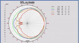
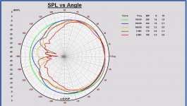
SPL plots on infinite baffle (grey), asymmetric position (blue), symmetric position (red) for tweeter and midrange .
Polar plots tweeter 2.5 - 12 kHz asymmetric and symmetric position.
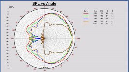
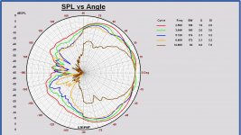
Polar plots midrange 160 – 2500 Hz asymmetric and symmetric position.
Some simulations plots to show the difference between an asymmetric versus a symmetric horizontal position of the drivers on the front baffle.
For the tweeter, SPL is better on axis, but a little worse horizontal polar.
For the midrange, SPL is the same on axis, but it is better horizontal polar.
In attach some plots.
SPL plots on infinite baffle (grey), asymmetric position (blue), symmetric position (red) for tweeter and midrange .
Polar plots tweeter 2.5 - 12 kHz asymmetric and symmetric position.
Polar plots midrange 160 – 2500 Hz asymmetric and symmetric position.
Attachments
-
 Polar H midrange 160-2500Hz symmetric.JPG195 KB · Views: 148
 -
 Polar H midrange 160-2500Hz asymmetric.JPG191.8 KB · Views: 159
 -
 Polar H tweeter 2.5-12kHz symmetric.JPG193.3 KB · Views: 155
 -
 Polar H tweeter 2.5-12kHz asymmetric.JPG195.2 KB · Views: 168
 -
 SPL midrange symmetric vs. asymmetric.JPG139.6 KB · Views: 181
 -
 SPL tweeter symmetric vs. asymmetric.JPG141.7 KB · Views: 532
I am curious about the Volt driver measurements.
I got the drivers. Had to carry a 20 kg parcel that was falling apart from the post office to my home. 😡
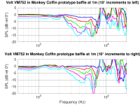
Anyway, here are the first measurement of the Volt VM752 on the prototype baffle from post 271. I don't have an IEC baffle, and my workshop is a mess. This means there was not a lot of space to make a clean measurement that was absolutely free of echoes, but it should be good enough to show the dispersion trends. At first sight, the results seem to be roughly consistent with Pauls simulations.
BTW.: the Volt VM752 are built like a tank. The ATC SM75-150 is already quite something, but the build quality of the Volts is even higher!
Attachments
Hi Matthias,
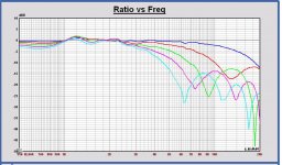
Great !! I did simulate now in the Monkey cabinet with the last front baffle, to the right with 10 deg steps also. Indeed very simular with your first measurements.
I had expected more impact of the waveguide. In your measurement there will be probably some extra diffractions of the front baffle.
Great !! I did simulate now in the Monkey cabinet with the last front baffle, to the right with 10 deg steps also. Indeed very simular with your first measurements.
I had expected more impact of the waveguide. In your measurement there will be probably some extra diffractions of the front baffle.
Attachments
How about imaging, loudspeakers with narrow baffles is said to image better then wide baffles, is there no truth to it?
How about imaging, loudspeakers with narrow baffles is said to image better then wide baffles, is there no truth to it?
I don't see why this would be the case.
... Is that resonant behaviour at ca 2200-2300hz somewhere? How does it look on the distortion plot?
So xo no higher than 2300hz?
Paul, you forgot to mention the main point of better group delay values where it counts, but I will stop now... 🙂
So xo no higher than 2300hz?
Paul, you forgot to mention the main point of better group delay values where it counts, but I will stop now... 🙂
Hi Kaffimann, yes group delay, of course, very very important, how could I forget to tell 🙂.
The resonances around 2.3 kHz, also visible in the simulation, are baffle diffractions. The simulated responses are normalized to the on axis response.
I did understand that Matthias' curves are normalized also and measured on the prototype baffle, not in a cabinet. My simulations are done in the cabinet model.
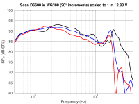
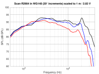
After I tried my Scan D6600 in a WG300 waveguide a while ago, I also tried the Scan R2904 in the WG300 and WG148 waveguides. Mating these drivers and waveguides is a bit of work, but doable (see here for the WG148, and here for the WG300; make sure to scroll down and also read the relevant follow-up posts).
I measured the SPL response and dispersion with the microphone 35cm away from the baffle. The baffle was 32cm wide, with the tweeter in the middle, 16cm from the top (yes, that's a "bad" position in terms of baffle-edge diffraction; and no, I didn't have the Monkey Coffin prototype baffle ready for these tests). The results (attached) were scaled to dB-SPL at 1m distance.
The on-axis is a wee bit bumpy below 10 kHz. I guess this is due to the baffle-edge diffraction, but I think this is not too bad given that the distance of the tweeters were centered relative to left/right/top edges!
There are some wiggles above 16 kHz, as discussed here. They are strongest for the D6600 in WG300, and "best" for the R2904 in the WG148. My ears will not hear these, so I don't worry too much about the >16 kHz wiggles.
While the D6600 is not loud enough for the Monkey Coffin, the R2904+WG148 does look like a suitable candidate. With an x-over of about 2 or 2.5 kHz it might also work out as a good match to the Volt VM752 in terms of dispersion.
What do you guys think?
Attachments
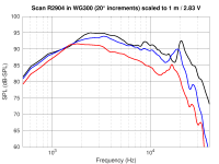
Looking to the datasheet of the R2904/700000, the sensitivity with waveguide at 2.83 Vrms will be even more than in your measurment, not ?
For me it is ok, good choice.
For me it is ok, good choice.
Looking to the datasheet of the R2904/700000, the sensitivity with waveguide at 2.83 Vrms will be even more than in your measurment, not ?
For me it is ok, good choice.
The datasheet says 94.5 dB/1m/2.83V, but the SPL graph in the datasheet looks more like 92 or 93 dB/1m/2.83. I also suspect that the drive voltage level in my measurement chain might be a bit off (I need to check).
Yes, but looking to the sensitivity above 10 kHz, it is 92 dB minimum and more in the datasheet. That is some loss in the waveguide then, because in your measurement it dips to 88 dB.
At 2 - 3 kHz there probably is some waveguide SPL gain and the SPL there is already 93 dB in the datasheet.
But only good news if it is more.
At 2 - 3 kHz there probably is some waveguide SPL gain and the SPL there is already 93 dB in the datasheet.
But only good news if it is more.
Looking to Scanspeak 2608, https://www.scan-speak.dk/datasheet/pdf/d2608-913000.pdf.
I think it can also be fixed simple to the Visaton WG148R. The front plate is flat and the 4 screws are on 92 mm diameter. The WG148R screws are at 94 mm diameter. So making the holes in the tweeter a little larger to 6 mm it must fit. Just like the Seas nonferro-900. And maybe there are even more candidates with the Visaton waveguide, just found now this Scanspeak.
But maybe it is a little more complex that that 🙂.
Edit: I see that more of the Seas Prestige series tweeters have a mounting diameter of 92 mm. So they could fit all on the Visaton waveguide...
I will have a closer look on that.
Last edited:
Meh. You would likely do much better with a 1 3/8 into the JBL Ewave WG. Sensitivity to burn too.What do you guys think?
- Home
- Loudspeakers
- Multi-Way
- Open Source Monkey Box