
UPDATE:
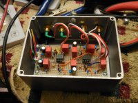
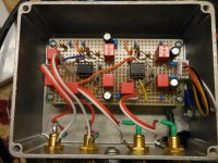
The box is done now sans the lid and probes are on the RCA outs. Whats there is a very clean and steady 50KHz sinewave with hash flying across the screen. The 50KHz signal gets much stronger (mV increases to 10s of mV) as I lift the lidless box up towards the bench's fluorescent tubes. The input RCAs are unterminated so all this is very prelim and not to get exited about. See attached pics as of today and a CORRECTED layout diagram from Post #506.
The box is done now sans the lid and probes are on the RCA outs. Whats there is a very clean and steady 50KHz sinewave with hash flying across the screen. The 50KHz signal gets much stronger (mV increases to 10s of mV) as I lift the lidless box up towards the bench's fluorescent tubes. The input RCAs are unterminated so all this is very prelim and not to get exited about. See attached pics as of today and a CORRECTED layout diagram from Post #506.
Attachments

OK, 1st but maybe not the last, impressions of the Marvel phono pre:
1) With the preamp cranked as high as I may ever go and with the tone arm on rest with mute switch Open (i.e. cart is connected to the Marvel) = Dead quiet. Nothing audible. No hum, no hiss with my ear to the tweeter.
2) Again, total silence when the mute switch makes or breaks - albeit this TT is a big brother of what I was using in 2021. Both are 40-year old Mitsubishi, full-auto, linear trackers. This one is the flagship LT-30 I finally repaired and put back into service. It may use a snap-action mute switch.
3) NO room-slosh. NO subwoofer cone flap movement at high or low volume settings. No info yet on record warp. Just the TT room feedback is gone.
4) Right and left Vos readings are +100uV and -200uV, resp. Spec for plastic DIP OPA627AP = 130 typ / 250 max.
5) For grounding I have all four RCA jack bodies mounted directly onto the aluminum alloy case. I also have the RCA's shield tabs wired to the internal PCB Signal Gnd(??) The PCB Signal Gnd comes from the case via its power plug 0V connection.. The case is bonded to the mid-point of the outboard +/- linear power supply via braid shielded (0V) twisted-pair (+/-) mic cable (i.e. the PS is floating). The TT's Gnd wire goes to the case. The case is then one-time-Earth-grounded through the interconnect shields to the 3-prong-grounded preamp Line input. So, the Marvel, its power supply, the TT's cable shield and frame are all tethered back to the main preamp's grounded input shield. That seems to work well, for me but I have no noise numbers.
6) All AC power cables plug into a multi-outlet power conditioner.
7) I will scope the Marvel's output and look for high-freq RF trash.
6) I know that the Marvel I built has a 2x midband gain (46dB) but I don't see that boost in the main preamp's volume control position and that seems very strange.
Kind of quiet here. I'm quiet and pissed b/c I broke off the gold-plated boron cantilever of my AT 150MLx cart today. Sad and bad.
Oh yea, last of a kind. I hadn't had it that long. Was still setting it up using test LPs and listening to the new pre amp. I think there is a replacement stylus - tapered aluminum pipe with the Shibata diamond. Whatever I do I'll have do ALL the setup AGAIN - Mounting and overhang, VTF, Azimuth, Zenith, VTA, stare at the scope for channel balance, crosstalk/separation, FR, resonance... ugh.
Is it worth it to sim injecting a Square Wave at the RIAA input preamp?
Which settings should be used? The same that you use to run a SW test on a power amp?
Which settings should be used? The same that you use to run a SW test on a power amp?
I have something to report re the Marvel phono preamplifier. Today with a new cart I started the setup rigmarole with the Analogue Productions test LP, side 1, track 1, 2 and 3 designed for chan/chan balance and crosstalk/separation using 1KHz as the signal. Track 1 puts equal signal on both L & R groove walls.
Attachments
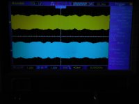
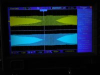
See AnalogProd S1-Tr1 - which looked clean but the scope could not lock-up the trace. It was dancing a bit like there was something else going on.
See 20mS-Div - which when the sweep was slowed from 400uS to 20mS revealed a possible 2nd signal mixed in.
See 80mS-div - which looks like the 1KHz from the LP is being modulated onto or by a lower frequency carrier.
See 400mS-div - which is the 1Hz ghost in the deep background. Track 1 is still playing, the 1KHz tone can be heard but there seems to be a warble.
This 1Hz phantom goes completely away when the needle is lifted (cart outputs shorted) or when on the arm rest (cart outputs = normal play mode). Scope shows a flat line at 5mV/div.
I believe I saw this when I did my first bench testing using a sig-gen and scope combo but attributed any funny stuff to the bench environment. Now I don't know. What could this be caused by? Marcel? Help please.
Attachments


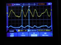
See 400mS-div - which is the 1Hz ghost in the deep background. Track 1 is still playing, the 1KHz tone can be heard but there seems to be a warble.
Why don't you see the 1 kHz component on this plot? What is the oscilloscope's sample rate for the various plots?
Unfortunately, I haven't a clue what is going on. You could get a pretty bad resonance when R7 is missing or not connected, but it should be around 16 Hz rather than 1 Hz.
Is 1 V on the scope 1 V in reality or is there a probe attenuation to be taken into account?
Is R6 properly connected?
Last edited:
This will probably not change anything, but if you haven't already done so, you could add an extra decoupling capacitor (100 nF X7R or so) straight from pin 7 to pin 4 of each OPA627. With the present decoupling, there is a rather big loop from the positive supply pin via its decoupling capacitor and three ground traces through the decoupling capacitor of the negative supply pin to the negative supply pin.
Record warp / eccentricity signal occurs (for 33rpm) at multiples of 0.55Hz - your waveform suggests 1.1Hz so this is likely warpage and eccentricity showing up - this is why a quality RIAA preamp has an aggressive high-pass filter "rumble filter" usually with a cut-off around 15 to 18Hz. The second harmonic is more likely to be warpage, eccentricity would be mainly fundamental.
However there are other ways subsonic signals can get in - perhaps there is subsonic acoustic noise in your area? Or less-than perfect platter geometry and bearing? Slipmat that's not super flat...
With a poor quality pressing these 0.55/1.1/1.65/2.2 etc Hz signals can damage (sub)woofer drivers if it passes straight through the amplifier chain un-filtered, especially in a ported speaker, causing high dissipation and end-stopping - even smaller amounts will inter-modulate in the driver with other wanted bass signals.
Rumble filters are often omitted phono preamps, I think they are an essential part of what a phono preamp should be doing. Something like a 4 or 6 pole Butterworth filter is an approach one can use with a single opamp. Bessel filters might be better behaved in the bottom octave, although less effective. I think either is reasonable, again about 15 to 18Hz cutoff is a reasonable choice.
The 400 ms/div waveform looks irregular. Shouldn't it repeat every 1.8 s (at 33.3333... rotations per minute) if it were due to warps or eccentricity? Left and right appear to be in phase, so eccentricity rather than warps then?
This specific phono amplifier has a built-in second- or third-order 16 Hz Butterworth high-pass filter. If I understand it correctly, JRA built the second-order version. The 1 Hz must be what is left after 48 dB of suppression from the subsonic filter then.
This specific phono amplifier has a built-in second- or third-order 16 Hz Butterworth high-pass filter. If I understand it correctly, JRA built the second-order version. The 1 Hz must be what is left after 48 dB of suppression from the subsonic filter then.
Why don't you see the 1 kHz component on this plot? What is the oscilloscope's sample rate for the various plots?
Unfortunately, I haven't a clue what is going on. You could get a pretty bad resonance when R7 is missing or not connected, but it should be around 16 Hz rather than 1 Hz.
Is 1 V on the scope 1 V in reality or is there a probe attenuation to be taken into account?
Is R6 properly connected?
I do not know why the 1KHz just disappears when I switch to slower sweep rates. Same thing happens using a different scope. I do not know what sample rate is used for either scope at the time of the scope shot.
R7 and R70 appear to be there, in-place.
The scope shots are with input = 1:1, direct in using BNC - BNC cabling. No "scope" cables and not 10:1. See hookup pic in #569
Yes, the vertical aspect is correct. 1V = 1V
R6 and R60 look good.
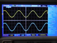
See attached
- Hantek scope: Yellow = Right chan Output during test LP 1KHz track 1. Blue = Right chan cart Input. They are the same. The 1Hz appears to be generated by the MM cart. 11mV in from cart and 2V out from preamp = 45.2dB = about right.
- Owon portable scope: Same thing as above at 500mS/div; in-phase, same voltages and same frequency - just a hair over 1Hz.
Both In or Out scope traces go flat between tracks as in no warp. Flat in the inner dead wax spiral as well.
I built the 3rd order JRA version with the very large 2.2uF input cap and I believe my version also used dual 6.8uF caps and a 232R in the feedback. I remember the 2nd order being different in both cases..? See attached schemo and matching layout.
I will now install my original TI-based phono preamp modified with a 3rd order at the front-end with input buffer and 47K resistive Zin. I'll also re-investigate the preamp's behavior at sub-8Hz freqs with a better sig-gen. I'll be back with a new post.
Attachments
I think the 400 ms/div plot from post #569 simply shows aliasing of your digital oscilloscope. The 1 Hz signal is just as large as the desired signal of the 200 us/div plot, as you would expect when it is an alias. If this hypothesis is correct, then slightly changing the turntable speed should change the frequency of that 1 Hz signal a lot: a 0.1 % speed change should change it by 100 %.
This doesn't explain the dancing of the signal at 200 us/div. Maybe that's some rumble that still comes through.
With C2 = 2.2 uF and R7 = 1.07 Mohm, the roll-off is second-order Butterworth. With 150 nF and 1.58 Mohm, it's third-order Butterworth.
This doesn't explain the dancing of the signal at 200 us/div. Maybe that's some rumble that still comes through.
With C2 = 2.2 uF and R7 = 1.07 Mohm, the roll-off is second-order Butterworth. With 150 nF and 1.58 Mohm, it's third-order Butterworth.
Last edited:
Well first off I don't know what aliasing means in this context. I've never seen a scope misbehave like this, ever. Second thing is that my original TI/1656 preamp design I built in 2021 showed-up the same exact way with the weird 1Hz signal with slow sweep rates. No different. And it now has a standard S-K 3rd order hi-pass bolted to the front end.I think the 400 ms/div plot from post #569 simply shows aliasing of your digital oscilloscope. The 1 Hz signal is just as large as the desired signal of the 200 us/div plot, as you would expect when it is an alias. If this hypothesis is correct, then slightly changing the turntable speed should change the frequency of that 1 Hz signal a lot: a 0.1 % speed change should change it by 100 %.
Attachement:
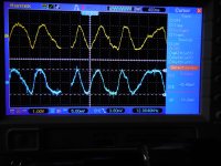
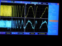
- Yellow on top = 1kHz LP test signal Vo from original pre. Left 1st quarter of screen = turntable slowed. Remaining screen = TT resuming speed.
- Blue on bottom = 1KHz LP test signal from cart. Ditto.......
Unbelievable! So you were right again Marcel but WTF does this all mean? Is it an artifact of the sub-sonic hi-pass filters used in both preamps? Same artifact showing up in two different scopes?
Could be. The TT is 40 years old. Or something floor-born? Fridge? HVAC blower motor...? The neighborhood is VERY quiet, however.This doesn't explain the dancing of the signal at 200 us/div. Maybe that's some rumble that still comes through.
Well, I must admit that in my old age, I administered your very clear instructions completely backwards. I can not believe I've gotten so so stupid. So yes, I built the 2nd order version using all the values in parens.With C2 = 2.2 uF and R7 = 1.07 Mohm, the roll-off is second-order Butterworth. With 150 nF and 1.58 Mohm, it's third-order Butterworth.
Is there anything to do now?
Attachments
Relax and enjoy the music? The large 1 Hz signal you saw was just a measurement artefact, and per post #563 point 3, the subsonic filtering appears to be sufficient for normal use.
The fact that you haven't seen aliasing of a digital oscilloscope before means you have been lucky up till last Friday. They all sample and they never have anti-aliasing filters, so you can always get to see something at the difference between the signal frequency and the sample rate rather than at the signal frequency. For that reason, a now retired colleague of mine used to look all over the lab to see if there was still a good old analogue scope left somewhere when he needed to measure something with an oscilloscope.
The fact that you haven't seen aliasing of a digital oscilloscope before means you have been lucky up till last Friday. They all sample and they never have anti-aliasing filters, so you can always get to see something at the difference between the signal frequency and the sample rate rather than at the signal frequency. For that reason, a now retired colleague of mine used to look all over the lab to see if there was still a good old analogue scope left somewhere when he needed to measure something with an oscilloscope.
Has anyone tried the AD4625-1 or -2? Specs on noise and offset look very good. Expensive though.
Oh for my childhood days of the big Tektronix on a cart. You want storage..? During one career there was the "baby scope". It was a small analog Tek scope with a neck strap, battery-powered and had storage. When sent to the field I always packed that thing in my luggage.The fact that you haven't seen aliasing of a digital oscilloscope before means you have been lucky up till last Friday.
Yup, that's right as well. 2nd order fooled me. It's very good enough. But I still wonder about that big 2.2uF the cart sees first.and per post #563 point 3, the subsonic filtering appears to be sufficient for normal use.
- Home
- Source & Line
- Analogue Source
- OPA1656 Phono Preamp: Split from OPA1656 thread