Mpsa 56 mpsa 06, mpsa 42 mpsa 92, mpsa 43 mpsa 93
Betther start looking at the smd side bc840 i bilelive it was.
For simmilar CFA input stage the NAd 214 and 216 is using 2sa970 2sc2240 in CfA. For inspiration if somone like too compare designs.
Another input stage with different current sett due too config is the Marantz HDAM sa3 a classical pice for a looong time....China suppliers sel hadam preamps for diyers on bay.
Hav a nice research.
Last edited:
Seems like everyone is busy now. RDijk, could you please say about pros and cons of your input stage and current LC input stage I'm using? I know that you might not had an ability to hear it, as I'm your input stage, but for just simulation specs.
I put 50pF for every BE of Q16, Q17, 25 Ohm driver's BE resistors and oscillations disappeared completely. Later before I tried such cap at BE of both VAS transistors, as RDijk recently sugested, but such combination had a lower effect than with single VAS transistor. Will try lower value later.
However recently I observed serious DC offset drift in the amp. After 5-10min of stand by DC offset drifts to 100-150mV. Also when I turn the amp off I have rapid DC spike on the speaker (over 2V at 2000mV DMM range, with higher range setting DMM can't detect it) by light whisle sound with woofer coil moving outward of magnet. I measured 1.05V\1.35V collectors voltage at Q16, Q17 at on state. Feedback resistors voltage drop 500mV\755mV. Maybe one of the VAS transistor beta is dropping during warm up time or there are some other reasons. Does anybody have and idea why there is such DC offset drift? Tnx.
Btw, RDijk, R5, R6 9K resistor trick against 11K with didn't work. The Leds are still off. It's not a problem for me, however, I can live with that, don't worry.
Last edited:
Thermal DC drift
DC drift is most likely from Q2,Q3 (input tr's) and Q6,Q7 (CCS tr's). While measuring DC out touch Q2 with your finger to warm it slightly. Repeat with Q6. You should find they cause opposite changes.
Q6 compensated Q2 (likewise Q7 compensates Q3). If these pairs get different temperature changes then it shows in the DC offset at the output, even only 0.1C difference can be noticeable.
If this is the cause then the solution is to 'strap' Q6 to Q2 (likewise Q7 to Q3). I assume Q6 and Q2 are not mounted together. Until you update the PCB, add flying wires to Q7, Q7 and strap them. 'Strap' means the TO-92 flats are together and they are best held firm with heatshrink and helps shield them from moving (warm) air.
Cheers
Good to hear you can get it stable. Try different types of compensation with and without Zobel and keep notes.I put 50pF for every BE of Q16, Q17, 25 Ohm driver's BE resistors and oscillations disappeared completely. ...
However recently I observed serious DC offset drift in the amp. After 5-10min of stand by DC offset drifts to 100-150mV. ...
DC drift is most likely from Q2,Q3 (input tr's) and Q6,Q7 (CCS tr's). While measuring DC out touch Q2 with your finger to warm it slightly. Repeat with Q6. You should find they cause opposite changes.
Q6 compensated Q2 (likewise Q7 compensates Q3). If these pairs get different temperature changes then it shows in the DC offset at the output, even only 0.1C difference can be noticeable.
If this is the cause then the solution is to 'strap' Q6 to Q2 (likewise Q7 to Q3). I assume Q6 and Q2 are not mounted together. Until you update the PCB, add flying wires to Q7, Q7 and strap them. 'Strap' means the TO-92 flats are together and they are best held firm with heatshrink and helps shield them from moving (warm) air.
Cheers
I put 50pF for every BE of Q16, Q17, 25 Ohm driver's BE resistors and oscillations disappeared completely. Later before I tried such cap at BE of both VAS transistors, as RDijk recently sugested, but such combination had a lower effect than with single VAS transistor. Will try lower value later.
However recently I observed serious DC offset drift in the amp. After 5-10min of stand by DC offset drifts to 100-150mV. Also when I turn the amp off I have rapid DC spike on the speaker (over 2V at 2000mV DMM range, with higher range setting DMM can't detect it) by light whisle sound with woofer coil moving outward of magnet. I measured 1.05V\1.35V collectors voltage at Q16, Q17 at on state. Feedback resistors voltage drop 500mV\755mV. Maybe one of the VAS transistor beta is dropping during warm up time or there are some other reasons. Does anybody have and idea why there is such DC offset drift? Tnx.
Well as anatech pointed out in a recent post strange things happen with a light bulb in series with the transformer primary winding.
The beta is drooping because the power supply is not working properly - you have no more than 180 m.a. of mains current with a 40 Watt bulb (40 W/220V ac mains) to magnetise the core or cores of one or two toroidal transfers.
If you are not getting anywhere with a 40 Watt bulb try increasing the wattage of the test bulb in steps.
I suspect the whistling noise is due to a heterodyne effect is a reaction due to differences in the toroidal transformer characteristics - resistance, inductance etc due to a change in the mains impedance.
Mpsa 56 mpsa 06, mpsa 42 mpsa 92, mpsa 43 mpsa 93
Betther start looking at the smd side bc840 i bilelive it was.
For simmilar CFA input stage the NAd 214 and 216 is using 2sa970 2sc2240 in CfA. For inspiration if somone like too compare designs.
Another input stage with different current sett due too config is the Marantz HDAM sa3 a classical pice for a looong time....China suppliers sel hadam preamps for diyers on bay.
Hav a nice research.
I use KSC1845/KSA992 in my Marantz based CFA power amplifier. They are very nice, cheap, so You can get lot of them to be able to select by Hfe. The Hfe is about 350-420 typically.
Sajti
Thanks for your answers Ian and Michael. Unfortunately the reason is not a input or ccs tr's, nor a light bulb (I'm using 100-150W bulbs). I tried to touch input and ccs tr's but it doesn't help, dc offset changes only from airflow on TO-126 VAS tr's. The voltages at cbe of TO-92 VAS tr's are the same, that means input and ccs tr's have equal current supplied to VAS, only bigger VAS tr's show the difference at collectors. It started to happen when I connected 150W 8ohm drivers to check the power out of the amp. Only after that i removed the oscillations with mentioned mods. Perhaps Q16, Q17 were overheated, as my copper heatsink was quite hot. Do you know how to measure real Pd of tr's in the circiut? Also, as I mentioned before, the amp consumes more current at positive main power rail, because when I turn it off positive output LED goes to off state the same time as frontend LEDS, while negative side LED continues to glow up to 5 min. Btw, when I reduce the input bias to 3mA, this effect with LED is less noticeable.
I'm sure this is not transformer or light bulb issue, because it happens in stand by mode without any input signal when 100w or 150w bulb doesn't glow at all. The whistle noise at full range speaker, hum noise at low frequency driver is due to high dc at out most likely. Before dc spike at power off was 200-300mV, now is much higher.
I'm sure this is not transformer or light bulb issue, because it happens in stand by mode without any input signal when 100w or 150w bulb doesn't glow at all. The whistle noise at full range speaker, hum noise at low frequency driver is due to high dc at out most likely. Before dc spike at power off was 200-300mV, now is much higher.
Last edited:
Hi Andriy,
The whistle is not caused by the DC offset, but it does sound like something is oscillating. The oscillation can cause low level DC offsets like you are finding. 'Scope time.
-Chris
The whistle is not caused by the DC offset, but it does sound like something is oscillating. The oscillation can cause low level DC offsets like you are finding. 'Scope time.
-Chris
Hi Chris.
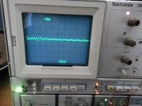
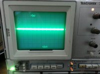
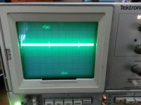
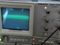
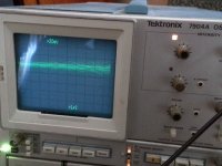
I checked the output with the scope and haven't seen the oscillations. Will upload the pics later. Perhaps oscillations are in range over 200MHz where my scope hasn't capable.
I forgot to mention, before with 300mV dc offset spike at output only little hum noise was heard before the voltage in the amp become completely off state, now the woofer cone moving added with little whistle sound.
Last edited:
The whistle could be a heterodyne effect.
You are still running a pair of toroidal transformers having differences in winding impedance and inductance both in the secondary and primary winding circuits.
These apparently from a single mains source via a light bulb which is still a higher impedance source than envisaged by transformer design science.
At the same time your nfb network has a relatively low impedance.
Re the spike and the whistle you would have to question whether the distribution between the two transformers is sufficient for the needs of one or other at various points of the mains frequency and whether the harmonics are all in tune in terms of phase.
My first thoughts were that a light bulb is often used in the feedback loop of an op.amp to make an oscillator and so the bulb is not restricted to operating at dc or ac. A complication here is feeding paired reactive loads which will generate two lots of varying back emf in the primary winding being presented to the light bulb.
This has implications for the linearity of the supply rails across the audio spectrum and possibly further out. Any such non-linearity here will find it's way into the nfb connection at the output.
Doing things your way something needs to change in order to obviate these possible causes.
A couple of things to try would be
1. Reverse the mains connection of one of the transformers so this is the opposite of the other feed. I have doubts this will do much but it might change the phase so there is less cross influence between the transformers.
2. A simulation the result shows the circuit will function if the whole thing is run on the same voltage supplies. This will take out any cross influence of transformer interaction.
You need to be able to get to a stage where is is possible to vary the output stage Iq to a safe low setting. Once you can do that then you can think about restoring the input stage rails to the higher voltage.
A third thought is to fit capacitors of 100n between each end of the transformer primary winding to the center tap to suppress ringing effects and to check your earth system for power and signal sources - to see this has not been compromised somehow in the in view of the many changes you have tried along the way.
I can try that. I even try to power on the amp with variac. I have to start with low output voltage and slowly raise it to say from 100 to 220VAC and listen the variac's noise if current consumption is in normal range? Or I can put 50 Ohm power resistor at variac out and check the current at that resistor by second dmm?1. Reverse the mains connection of one of the transformers
2. A simulation the result shows the circuit will function if the whole thing is run on the same voltage supplies.
You need to be able to get to a stage where is is possible to vary the output stage Iq to a safe low setting.
I already have 2.2nF on rectifiers output. I can change them to 10n or 100n or put them directly on secondaries, as you advised. However I read somewhere that it's not recommended to put caps at transformer's secondaries or primary, better to do it on rectifier's out. For the small front end transformer 10nF caps are implied by the schematic in parallel to every 4 input diodes.
What do you mean by ' to get to a stage where it is possible to vary the output stage Iq to a safe low setting?'
Last edited:
I added the recording of the sound from speaker when the amp turned off and scope photos where 3 without input signal, 3 with music playing.
Attachments

Like Hegglund is typing !
Input current sorces and even the resistors feeding input current sorces have to be equal.
temp variation in input stage causes change in vas stage bias. That causes driver and output bias change.
But concern is different current consumption from power supply's.
( WAT IS NOT SYMETRIC ????? or getting symetric compensation )
My experience is that symetric input and symmetric driven vas stage is best stabilized with vas loading, ie cap near drivers base.
Last edited by a moderator:
Btw, after R5, R6 resistor change from 11K to 9.1K the voltage drop at LEDs become 1.38V. Perhaps I need to increase R5, R6 to get 1.8V on LEDs?
Regarding the amp, even with different power consumption on voltage rails with increased input bias, output DC was equal before. Now it starts from -50mV and stops at +150mV when predrivers' heatsink is hot. I suspect partial damage of VAS transistors which are the hottest part in the amplifier.
VAS loading is to use the caps from drivers' bases to gnd? What's cap value? This is similar to what IanHegglun advised to use shunt compensation at driver bases to reduce crossconduction effect. But in this case, as Keantoken mentioned, PSRR suffers, One of the Top Solid-State CFA amp design.
Perhaps I need to use 1W case Zeners?
Once Roender wrote about front end psu zeners 'any Zeners diode pakaged in less than 1W case and with Vr > 5v will be fully on reverse conduction for Ir >= 0.2...0.5 mA. There is no need for higher current trough a reverse polarized PN (or NP) silicone junction in order to have a true avalanche conduction and far away from the noisy corner of the reverse I/V curve'
I can try that. I even try to power on the amp with variac. I have to start with low output voltage and slowly raise it to say from 100 to 220VAC and listen the variac's noise if current consumption is in normal range? Or I can put 50 Ohm power resistor at variac out and check the current at that resistor by second dmm?
I already have 2.2nF on rectifiers output. I can change them to 10n or 100n or put them directly on secondaries, as you advised. However I read somewhere that it's not recommended to put caps at transformer's secondaries or primary, better to do it on rectifier's out. For the small front end transformer 10nF caps are implied by the schematic in parallel to every 4 input diodes.
What do you mean by ' to get to a stage where it is possible to vary the output stage Iq to a safe low setting?'
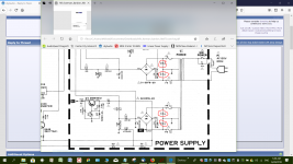
I have attached a circuit which illustrates my point about 100n resistors. You might like to consider the mains voltage suppressor cap across the mains switch too.
If your pre-driver stage is too hot to handle the answer to Iq adjustment possibilities is no.
Measure the voltage drop across R10 and R11. The current through these affects the base voltage and currents for Q16 and Q17 and if the drop is too great the latter will be driven harder.
Also if the current to the front end is restricted by a light bulb it is likely that more of that is flowing through these resistors rather than the 2k2 ones feeding your LED's.
You could try those values for R10 and R11.
This will mean the 15V zeners will be dropping to a fraction of their nominal voltage - but don't fret as you are looking for causes and effects.
In the end you could end up with a resistor zener combination where the latter is a substitute with roughly half the 15V nominal figure.
It was hapenning with me too. Perhaps you typed for too long and the site log you off. You shiuld always copy the text before sending it out.I had to rewrite my original post which included this. Both disappeared somehow before I could sent the reply.
These capacitors must be rated for mains use like Y1 or X1?I have attached a circuit which illustrates my point about 100n resistors.
If your pre-driver stage is too hot to handle the answer to Iq adjustment possibilities is no.
Measure the voltage drop across R10 and R11. The current through these affects the base voltage and currents for Q16 and Q17 and if the drop is too great the latter will be driven harder.
Also if the current to the front end is restricted by a light bulb it is likely that more of that is flowing through these resistors rather than the 2k2 ones feeding your LED's.
In the end you could end up with a resistor zener combination where the latter is a substitute with roughly half the 15V nominal figure.
My base voltage drop is about right: 14.95V\15V. R10, R11 which are 1K are sufficient to supply enough current to zeners. I used these values with 8 input tr's, now is half of them. I can see voltage drop at 15V zeners only when light bulb is shining. I can even supply front end psu directly to mains, no problem with that.
By Iq adjustment possibilities do you mean changing current rating of front end psu or 25r at drivers' BE?
What resistor zener combination do you mean?
Last edited:
Btw, after R5, R6 resistor change from 11K to 9.1K the voltage drop at LEDs become 1.38V. Perhaps I need to increase R5, R6 to get 1.8V on LEDs?
Regarding the amp, even with different power consumption on voltage rails with increased input bias, output DC was equal before. Now it starts from -50mV and stops at +150mV when predrivers' heatsink is hot. I suspect partial damage of VAS transistors which are the hottest part in the amplifier.
VAS loading is to use the caps from drivers' bases to gnd? What's cap value? This is similar to what IanHegglun advised to use shunt compensation at driver bases to reduce crossconduction effect. But in this case, as Keantoken mentioned, PSRR suffers, One of the Top Solid-State CFA amp design.
Perhaps I need to use 1W case Zeners?
Once Roender wrote about front end psu zeners 'any Zeners diode pakaged in less than 1W case and with Vr > 5v will be fully on reverse conduction for Ir >= 0.2...0.5 mA. There is no need for higher current trough a reverse polarized PN (or NP) silicone junction in order to have a true avalanche conduction and far away from the noisy corner of the reverse I/V curve'
Yes vas loading is cap from vas transistor collector to GND. in the example i gave with werry capasitive load and without output ind+R. ( part of output zobel foor som.
The values vas 330pF from each vas colector (the swinging) to gnd. AND a cap 100pF from each base VAS transistor to vas colector out. ( the load was 1uF to gnd and som palell resistor .
Yes anny compensation vil reduse open loop gain and therfore reduse anny correction. Now your talking nyances biond stable. Compensation caps copled to psu is a other possibillity since psu should bee considered zero output impedance.
So my values may bee divided between psu and gnd. so abt 180 pF each vas colector to gnd and 150pF to psu. maybee there is som pros and cons ?
Regarding current tracking from current sorce and its temperature variations. With buffered feeback this effect is halved, the effect caused by input stage temperature effect is teoreticaly gone.
ur'e shure the psu is wired like this? see att.
I find that redusing R5 and R6 should give more "LED bias".
Attachments

A third thought is to fit capacitors of 100n between each end of the transformer primary winding to the center tap to suppress ringing effects and to check your earth system for power and signal sources - to see this has not been compromised somehow in the in view of the many changes you have tried along the way.
It was hapenning with me too. Perhaps you typed for too long and the site log you off. You shiuld always copy the text before sending it out.
These capacitors must be rated for mains use like Y1 or X1?
My base voltage drop is about right: 14.95V\15V. R10, R11 which are 1K are sufficient to supply enough current to zeners. I used these values with 8 input tr's, now is half of them. I can see voltage drop at 15V zeners only when light bulb is shining. I can even supply front end psu directly to mains, no problem with that.
By Iq adjustment possibilities do you mean changing current rating of front end psu or 25r at drivers' BE?
What resistor zener combination do you mean?
You will have to consult the electrical code in your country for any capacitor connected to the mains.
I don't want to speculate about the resistor zener combinations until you have settled the voltage rails for the front end.
If the front end supply voltage is too high with the transformer connected to the mains you could try putting some low value resistance or inductance between your bridge rectifier outputs and the capacitors. If the need is for 100 ma for example then 100R would drop 10V. That could be a reasonable starting value - although I don't know what your latest simulation indicates the actual draw for one channel will be. You can work with that and do the calculations.
A 470 uH Through hole powdered iron suppression choke has a resistance of 82 mR you could try this in combination with a resistor to knock some ragged edges off the top of the capacitor charging currents.
You could build such a filter around a suitable pair of tag strips.
I have a Class A amplifier that has 30,000uF capacitors in the supply which feed a pair of regulators. The transformer voltage for this was a little too high and I needed to reduce this for the sake of avoiding overheating the regulators. Fitting chokes between the rectifier and the capacitors is one of the best things I tried that improved the sound as well as reducing the transformer output voltage.
- Home
- Amplifiers
- Solid State
- One of the Top Solid-State CFA amp design