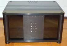
A friend of medid purchase this device last week in not perfect working condition (distortion at one channel).
Who can upload a schematic or know the type of used DAC chip and operational amplifier IC's for the I/U converter ?
On the web there are not many papers (only in German language) and no test reviews:
HORCH-REFERENZ
http://www.horch-gmbh.de/Produkte/STREAM_A5.pdf
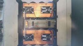
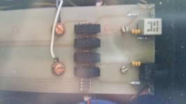
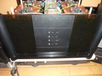
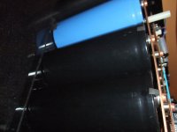
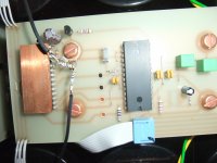
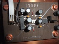
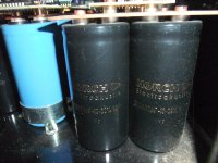
In the attachment you will find some images from internal used PCB's and (very large) capacitors with screw terminals.
There is additional an outdoor power supply, not showed here.
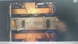
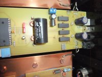
According the PCB's on the photos there are follow IC's in use (unrecognizable resp. defaced - Label was sanded off):
1) Receiver Chip (maybe CS8416 or similar)
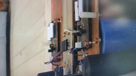
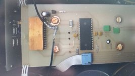
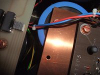
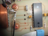
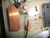
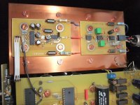
2) DAC chip with integrated digitalfilter (covered with copper sheet)
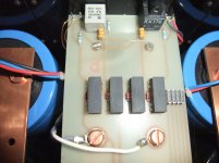
3) operational amplifier for I/U converter and low pass filter
for the reading of file naming, please log out
Thank you.
Who can upload a schematic or know the type of used DAC chip and operational amplifier IC's for the I/U converter ?
On the web there are not many papers (only in German language) and no test reviews:
HORCH-REFERENZ
http://www.horch-gmbh.de/Produkte/STREAM_A5.pdf
In the attachment you will find some images from internal used PCB's and (very large) capacitors with screw terminals.
There is additional an outdoor power supply, not showed here.
According the PCB's on the photos there are follow IC's in use (unrecognizable resp. defaced - Label was sanded off):
1) Receiver Chip (maybe CS8416 or similar)
2) DAC chip with integrated digitalfilter (covered with copper sheet)
3) operational amplifier for I/U converter and low pass filter
for the reading of file naming, please log out
Thank you.
Attachments
-
 Horch DAC model STEPS1.jpg63.5 KB · Views: 1,531
 -
 Horch DAC STEPS1-Top-View-I.jpg41.2 KB · Views: 1,554
 -
 Horch DAC STEPS1-Top-View-II.jpg43 KB · Views: 1,519
 -
 Horch DAC STEPS1-Top-View-III.jpg42.7 KB · Views: 1,537
 -
 Horch DAC STEPS1-Top-View-IV.jpg40.4 KB · Views: 1,489
 -
 Horch DAC STEPS1-Capacitors.jpg45.2 KB · Views: 812
 -
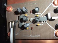
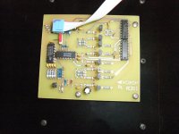
 Horch DAC STEPS1-input-selector.jpg33 KB · Views: 792
 -
 Horch DAC STEPS1- SPDIF-input-DAC.jpg40 KB · Views: 826
 -
 Horch DAC STEPS1-Filter.jpg43.2 KB · Views: 802
 -
 Horch DAC STEPS1-IU.jpg40.7 KB · Views: 816
Last edited:
2) DAC chip with integrated digitalfilter (covered with copper sheet)
Hmmm, I see only one of those chips, whereas the docs in your links seem to imply several paralleled DAC chips.
A friend of medid purchase this device last week in not perfect working condition (distortion at one channel).
Who can upload a schematic or know the type of used DAC chip and operational amplifier IC's for the I/U converter ?
On the web there are not many papers (only in German language) and no test reviews:
HORCH-REFERENZ
http://www.horch-gmbh.de/Produkte/STREAM_A5.pdf
In the attachment you will find some images from internal used PCB's and (very large) capacitors with screw terminals.
There is additional an outdoor power supply, not showed here.
According the PCB's on the photos there are follow IC's in use (unrecognizable resp. defaced - Label was sanded off):
1) Receiver Chip (maybe CS8416 or similar)
2) DAC chip with integrated digitalfilter (covered with copper sheet)
3) operational amplifier for I/U converter and low pass filter
for the reading of file naming, please log out
Thank you.
why doesnt he contact Horch ?
A test CD and an osziloscope should give you better insight in two minutes.
There is nothing more easy than to find a fault in a stereo system where one channel is working.
After checking the power supply voltages, you should do the following:
Give it a clean sinus from the CD and look at the output signals. My first test point would be the input of the analog output stage.
This way you know what you need to do now: Fix the analog side or the digital one.
If it is analog (OP-amps fail!) you can concentrate on finding out what IC it is.
If the digital side distorts, go back to the DAC output and make sure it is not one of the very few parts, but the IC itself. Then find out which DAC chip you got.
This high end rip off DAC contains basically air and electrolyth. What is a pitty for the one who once bought it, makes repair a breeze.
check out post #864 underwhy doesnt he contact Horch ?
Gestorben ist ...... - Seite 44 - Musik - allgemein - Analogue Audio Association
and this thread:
Reparaturservice fur Horch-Elektroakustik - Verstarker, Lautsprecher, Zubehor - Analogue Audio Association
CS4328 isn't available in a dual in line case resp. dual in line outline.DAC could be a CS4328?? the only big cap, maybe VREF, beeing visible is near pin 28??
There are no SO-8/SO-16/SO-24 parts in use
I guess, IC parts are in use as follow:
YM3623 (Yamaha) or Crystal CS8412 (SPDIF Receiver)
PMD100 (Pacific Microsonic) or DF1700 (Burr-Brown)
PCM1702 (Burr Brown).
AD846 (I/U resp. I/V converter)
Because there are no IC's with SMD resp. SMT outline (SO case) is to find, the number of types in question is not all that big.
The implementation/construction of this DAC is, uh, unusual.
You are so kind 😀
The approach reminds me of AN: concentrate on the analogue side and PS and completely ignore anything digital. That's the best recipe for "analogue" sound 🙄
Cannot imagine anything easier to repair or reverse engineer than this. The opamps will likely remain a mystery but the dac chip should be really easy to decode once a circuit is drawn.
CS4328 was available as DIP28, but OK, I saw the DAC must be on the black PCB, so yes, could be a PCM1702. The IC under the copper then will be a DF.
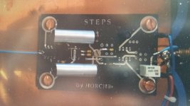
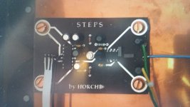
Images with higher Resolution Horch Model " S T E P S 1 "
The DAC was arrived to the new user and I have make own images:
The DAC was arrived to the new user and I have make own images:
Attachments
-
 DSCF5279.jpg1,011.5 KB · Views: 664
 -
 DSCF5273.jpg1,009.9 KB · Views: 663
 -
 DSCF5281.jpg980.7 KB · Views: 605
 -
 DSCF5283.jpg983.3 KB · Views: 602
 -
 DSCF5271.jpg978.5 KB · Views: 615
 -
 DSCF5269.jpg865 KB · Views: 437
 -
 DSCF5267.jpg979.2 KB · Views: 487
 -
 DSCF5265.jpg952.5 KB · Views: 403
 -
 DSCF5263.jpg1,003 KB · Views: 406
 -
 DSCF5261.jpg995.7 KB · Views: 417
Last edited:
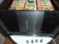
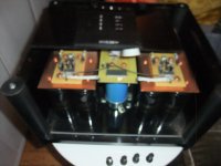
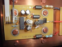
DAC Model " S T R E A M " - internal Images
The smaller model from this manufacturer was called STREAM, which the user had previously used and has a very similar construction. I have also disassembled that device for making images.
Probably next year I will try to create the schematics of both.
The smaller model from this manufacturer was called STREAM, which the user had previously used and has a very similar construction. I have also disassembled that device for making images.
Probably next year I will try to create the schematics of both.
Attachments
-
 DSCF5285.jpg1,013.5 KB · Views: 468
 -
 DSCF5303.jpg979.9 KB · Views: 296
 -
 DSCF5299.jpg1,005.4 KB · Views: 325
 -
 DSCF5301.jpg1,023.3 KB · Views: 311
 -
 DSCF5297.jpg999.8 KB · Views: 328
 -
 DSCF5295.jpg1,006.1 KB · Views: 365
 -
 DSCF5293.jpg1,008.4 KB · Views: 362
 -
 DSCF5291.jpg1,003.7 KB · Views: 380
 -
 DSCF5289.jpg985 KB · Views: 365
 -
 DSCF5287.jpg987.3 KB · Views: 416
Last edited:
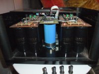
The implementation/construction of this DAC is, uh, unusual.
Uhhhhhhhh, yeah...looks like the PSU of a power amp!
The smaller model from this manufacturer was called STREAM, which the user had previously used and has a very similar construction. I have also disassembled that device for making images.
Probably next year I will try to create the schematics of both.
Why don't you try emailing this guy and see if he has the schematics?
Wizard High-End Audio Blog: Horch Reference Steps 1 & 2 Dac
All those caps could potentially be too old and will need to be replaced.
Good luck,
Greg
You are so kind 😀
The approach reminds me of AN: concentrate on the analogue side and PS and completely ignore anything digital. That's the best recipe for "analogue" sound 🙄
Cannot imagine anything easier to repair or reverse engineer than this. The opamps will likely remain a mystery but the dac chip should be really easy to decode once a circuit is drawn.
Yes, but also the quality of caps. Solen are very averaging sounding caps. Why spend so much on power supply caps and so little on decoupling, it makes no sense.
Also you need big cans when the ripple current is big, these are an unnecessary cost IMO and take up lots of real estate. For a dac snap-ins would be a better fit. I also find the practice of removing chips markings a little cynical, if I buy a dac I want to know the chip it uses, maybe that's just me.
In general this can always happen, but not in this case by the use of caps from ftcap with screw terminals.Why don't you try emailing this guy and see if he has the schematics?
Wizard High-End Audio Blog: Horch Reference Steps 1 & 2 Dac
All those caps could potentially be too old and will need to be replaced.
Good luck,
Greg
A first step in preparing the circuit diagram is to get an overview of which ICs are suitable.
Therefore this list is helpful:
CD-Player-DAC-Transport List
Here are follow kind of ICs in use:
1) S/P-DIF Audio Interface Receiver (DIR) - outline/case/package:
dual in line 28 pol. - the following types are possible:
CS8412, YM3623B
2) digital filter (DF) - outline/case: dual in line 28 pol - the following types are possible:
DF1700, PMD100, various NPC versions like SM5813 and SM5843
3) the actually DAC-IC - the following types are possible:
PCM56, PCM1702, AD1851, AD1856, AD1860, AD1861, AD1862
4) I/U converter:
AD844
Sanding off code’s from chips is a strange way of protection. Don’t think he has service manual available. 🙂 Those MKM cap’s brings back memories.. I would start measuring on the analog part. Could be a missing/low opamp power. With a scope it must be an easy find because you have a working channel.
Sanding off code’s from chips is a strange way of protection. Don’t think he has service manual available. 🙂 Those MKM cap’s brings back memories.. I would start measuring on the analog part. Could be a missing/low opamp power. With a scope it must be an easy find because you have a working channel.
Lots of manufacturers sand off codes, keeping their device of choice a secret! 🙄
Yesterday I have create the circuit diagram. With help of the datasheets I have find out the used ICs:CS4328 isn't available in a dual in line case resp. dual in line outline.
There are no SO-8/SO-16/SO-24 parts in use
I guess, IC parts are in use as follow:
YM3623 (Yamaha) or Crystal CS8412 (SPDIF Receiver)
PMD100 (Pacific Microsonic) or DF1700 (Burr-Brown)
PCM1702 (Burr Brown).
AD846 (I/U resp. I/V converter)
Because there are no IC's with SMD resp. SMT outline (SO case) is to find, the number of types in question is not all that big.
S/P-DIF Receiver: CS8412
Digital filter: DF1700
DAC: PCM1702
I/U: maybe AD844
But unfortunately both usually 8 pin P-DIP outline from the output stage with 6db high pass filter are not usual operational amplifiers.
Very special are the using of pins 2 and 1:
PIN 2 is not connected (i. e. no NFB resistor network is present) and PIN 1 is together with PIN 4 on the negative voltage (-15VDC). The other pins are in use as usual on single op-amps, i.e. PIN 3 = input, PIN-6 = output and PIN-7 on the pos. voltage (+15VDC)
Are there operational amp versions with only one input and an integrated NFB network ?
Thank you for an advice.
Last edited:
- Home
- Source & Line
- Digital Line Level
- One of German's most ultimate DAC: Horch "STEPS 1" - Schematic wanted