Now I have just tried it but without any tweaks like filament bias etc.I've never exceeded 250v a-k with the 4P1L - that's what the data says. I think Ale Moglia tried it hotter but then went back to around 250v a-k. Something on his blog Bartola Valves maybe. But with 250v a-k you can certainly use 35mA. Try it and see if you like it. I always use Rod Coleman regulators for the 4P1L, as do most readers here I think. Not expensive and well worth it. I would use filament bias so you don't need a cathode bypass cap. Plenty of schematics on this thread.
Even if you change to another output tube like 300b etc, Rod's regs are still good. But the 300b won't be in filament bias. That's just a trick you can use with the 4P1L because of the low bias voltage.
Im using ac heating on the 4P1Ls, the hum is there but I will replace this with sigma 11 heater regulators which I have on hand. Operating point is something like 240V 40mA - little bit over 9 watts but the tubes dont suffer.
For driver Im using E180F triode connected biased with normal resistor in anode, But Ale Moglia sent me some gyrator and source follower boards - thank you very much for this nice gift! The E180F is biased with one red LED in cathode, I will soon try sic diodes instead.
The power supply is oversized withbig transformer and 30H choke input. I used oil filled capacitors on all place.
Before I was using 4654 IDH tube connected as triode and single 4P1L is a big improvement altough Im still using normal cathode bias. I had problem with weak bass but after putting the 4P1L into 40mA/240V this is not a problem.
Now I will try several tweaks to the amp. Andy, I have thought about filament bias in the power stage, but why not use simple fixed bias? Im scared by the large resistors and filament supply when using filament bias.
Andy, I have thought about filament bias in the power stage, but why not use simple fixed bias? Im scared by the large resistors and filament supply when using filament bias.[/QUOTE]
Nothing to be worried about. You need about 18.5v on the cathode. Run each 4P1L with heaters in series, then parallel them up. I use choke input for my filament supplies but you don't have to. Makes a nice upgrade not having a cathode bypass cap. I use Russian 10W silver coloured military resistors but Welwyn vitreous enamel are OK too. They need to be well oversized.
Nothing to be worried about. You need about 18.5v on the cathode. Run each 4P1L with heaters in series, then parallel them up. I use choke input for my filament supplies but you don't have to. Makes a nice upgrade not having a cathode bypass cap. I use Russian 10W silver coloured military resistors but Welwyn vitreous enamel are OK too. They need to be well oversized.
Andy, I have thought about filament bias in the power stage, but why not use simple fixed bias? Im scared by the large resistors and filament supply when using filament bias.
Nothing to be worried about. You need about 18.5v on the cathode. Run each 4P1L with heaters in series, then parallel them up. I use choke input for my filament supplies but you don't have to. Makes a nice upgrade not having a cathode bypass cap. I use Russian 10W silver coloured military resistors but Welwyn vitreous enamel are OK too. They need to be well oversized.[/QUOTE]
Okay, I will surely try filament bias one day but what about the fixed bias? Wont two 9V batteries in series do the same job?
Thanks. Best regards, Michal
Hello guys, on the vacation Ive tried fixed bias so I could get rid of the cathode cap in the output stage.
My listening impressions are, that the fixed bias sound more natural and more focused and real, just like Andy says with the filament bias, but the highs seems more harsh and dirty, I dont know why, but maybe because the rectifying diode switching, or something like that.... So yes, I now undrstand why you recommend filament bias - because it is totally noise free from the beginning.
How to do properly the fixed bias?
Best regards, Michal
My schematic is hereThat doesn't sound right. How did you implement the bias arrangement?

I tried using SIC diodes on the 4P1L cathodes, but preferred filament bias in this case. I do use SIC diode bias on my 26 input stage. MikyK describes the highs as harsh and dirty, and you can get that kind of slightly edgy sound with solid state devices. Sometimes more obvious, sometimes only barely obvious or perfectly acceptable depending. I found that SIC diode bias on both stages did give an edgy sound, so put the 4P1Ls back to filament bias.
QUOTE=andyjevans;6036749]I tried using SIC diodes on the 4P1L cathodes, but preferred filament bias in this case. I do use SIC diode bias on my 26 input stage. MikyK describes the highs as harsh and dirty, and you can get that kind of slightly edgy sound with solid state devices. Sometimes more obvious, sometimes only barely obvious or perfectly acceptable depending. I found that SIC diode bias on both stages did give an edgy sound, so put the 4P1Ls back to filament bias.[/QUOTE]
Yes. I tried a silicone diodes in b+ rectification, and the results were the same. More harshy and edgy. But in the rectifier and fixed bias supply I used cheap diodes. Maybe when I will use sic diodes in the fixed bias rectification, the results will be better. I use LED bias in my input stage and I like the sound of it. One of small things that dont changed in my amp for a long time.
P.S. it was just an experiment, with the hv rectifier. Normally Im using a pv200/600 rectifier which I like A LOT.
It is amazung that the dirty edgy sound is sometimes good and somethimes bad just like you describe. On some instruments the edge seems more right but at the same time in the highs it looses its amazung clearness and airyness.
Last edited:
My schematic is here
Are you sure, that with these small capacitors the bias voltage is enough clear?
Using two bias potentiometer in the same negative voltage is "old school" method. Any change in one affects the other.
Why not use proper filtration and independent bias circuits?
Sample:
Attachments
fixed bias supply I used cheap diodes...
UF4007 is enough good there. I used these diodes for decades in my fixed bias power supplies.
Okay. Thank you for the schematic.UF4007 is enough good there. I used these diodes for decades in my fixed bias power supplies.
I use some really normal slow diodes, but UF4007 is a fast diode as I know... I know that even 200uF in the whole bias supply is enough because there is absolutely NO HUM. Only the high frequency problem.
Maybe bypassing each diode with a 10-100nF ceramic cap will lower the problem a bit.
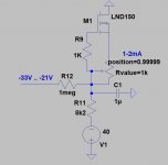
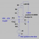
Can you please describe me which leg of the circuit is input, output, gnd, etc? Thank you very much.
Can you please describe me which leg of the circuit is input, output, gnd, etc?
khmmmm....
Attachments

Hello guys. Now I have just added second 4P1L to paralell. And it plays slightly less loud than before. Do you think that adding the second could attenuate the signal? Or something simillar, or I have just some mistake in my amp?
Thanks for answer
Thanks for answer
Ale, I'd like to try this configuration. Did you end up modifying the circuit to use three 4P1L? Would you care to explain what mods it would require? (I have a 2.5 K output transformer)
This is how I'd rebuild my previous 4P1L PSE with fixed bias and A2 drive:
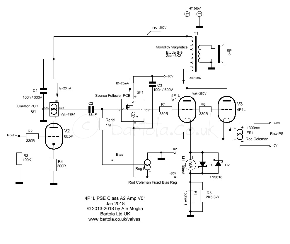
The driver is the 6e5p (or better 6e6p-dr) which is very linear and works well with a bit of degeneration in the cathode. As the stage is a hybrid mu-follower (i.e. gyrator load) the reflected cathode resistor in the anode isn't impacting the output impedance. The follower is a classic MOSFET (high GM, low Crss) follower using a symmetric +/-80V to provide enough headroom. The HT is a bit marginal for the driver but provides good headroom for the 4P1L.
The rest of the circuit is self explanatory
As I don't need the A2 power, I end up with the 4P1L PSE with filament bias I have now. Probably will rebuild this version as the follower drives well the PSE pair. I'd go for 3 valves next time.
Hope this helps.
Cheers
Ale
Hello guys, Ive got a pair of 45 tubes from friend of mine and tested them. Im quite a shocked because I think 4P1L is better 😱
Well, what doesn't surprise me is that a 4P1L in SE or PSE with filament bias could sound better than conventional resistor with bypass cap. I never tried a 45 but it would not be very conducive to filament bias.
Right now I have 45 tube with regular bypass cap and resistor, maybe it will be better with fixed bias, but I dont know.... As a driver I use 6N23P SRPP (same driver as I used with 4P1L dc coupled amp) which is capacitor coupled to the 45. Maybe its the bypass cap or the driver distorting (it must generate twice output voltage now) which is wrong.
Ive got two KC1 telefunken tube (dht with amplification of 30), and I can try it as a driver to drive 4P1L....
And trust me, DC coupled sounded (with 4P1L) really good even with the bypass cathode cap.
but I want to test something really different: using a voltage regulator tube instead of the cathode resistor and cap!
Last edited:
- Home
- Amplifiers
- Tubes / Valves
- One more 4P1L SE