Thanks, we better take care of ourselves. 😀Thanks guys and take care of coronavirus, here we are confined.
After playing a bit with penthode mode PL82 CFB + UL connection and a bit of local driver NFB, I'm thinking about a 4P1L 2PSE, again CFB + UL penthode mode.
The sound from a heavy CFB amp is really great and I prefer it versus pure triode connection.
What do you think about it?
The sound from a heavy CFB amp is really great and I prefer it versus pure triode connection.
What do you think about it?
I think that you are on the right path. Local feedback around pentodes does wonders. However, I would think twice about adding UL. ;-)
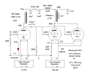
Today I finished off a 300b amp. Not optimised, but a decent build. Lundahl OPT, Rod Coleman regs on the filaments, cathode bias with large polypropylene bypasses. 2 stage, with a EF180 with a gyrator and SIC diode bias.
Not even in the ballpark with my PSE 4P1L build with 26 first stage. I abandoned 300b amps years ago and this hasn't really changed my conclusion that an all-DHT 2 stage amp with filament bias on the PSE 4P1Ls will out-sound a 2 stage 300b build with the inevitable indirectly heated driver.
Here's my current 4P1L PSE:
Attachments
Today I finished off a 300b amp. Not optimised, but a decent build. Lundahl OPT, Rod Coleman regs on the filaments, cathode bias with large polypropylene bypasses. 2 stage, with a EF180 with a gyrator and SIC diode bias.
Not even in the ballpark with my PSE 4P1L build with 26 first stage. I abandoned 300b amps years ago and this hasn't really changed my conclusion that an all-DHT 2 stage amp with filament bias on the PSE 4P1Ls will out-sound a 2 stage 300b build with the inevitable indirectly heated driver.
There is no inevitability about an indirectly heated driver in a 300B amp. Why don’t yo do what Vinylsavor and others do, use a stepup input transformer and a DHT driver. A 1:4 stepup and a 4P1L would probably do.
Does anyone have a schematic for a very simple 4P1L set i could knock up with parts i have lying around? i have several suitable power transformers, 5k set output transformers, coupling caps. Id likely rebuild with coleman regs, interstage transformers etc later (after this covid business is done and dusted)
boli46 - that's a really good idea and I should try it. I must have some kind of input transformers I can use. Thanks for that.
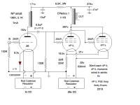
As for a "simple" 4P1L SET, the minimum I would build is a PSE output stage in filament bias. Anything else is false economy. You need to plan these things from the start. Preferably with outboard power supply and filament supplies. Here's a slightly different version of my current build
As for a "simple" 4P1L SET, the minimum I would build is a PSE output stage in filament bias. Anything else is false economy. You need to plan these things from the start. Preferably with outboard power supply and filament supplies. Here's a slightly different version of my current build
Attachments
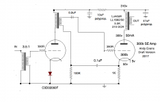
i have rebuilt the input of my 300B
simple 5R4 with CLC power supply
300V 60ma on the 300B with cathode Bias ( no ultrapath i don't like it)
rod coleman regulator for the filament.
so i swap my 91a like input stage with WE310a in pentode mode at 3ma
to a single 26 tube with filament bias , and CCS load at 4.5ma
with the low gain of the 26 i only have 1w output max but i have a 98db speaker i don't care. i will try the lundahl choke input step up option later.
what to say : with the pentode W310 or 6J7 the tone is better more rich i think
it seems simplified with the DHT , the 26 have also less bass than the pentode but more tight. image and instruments separation are far more prononced with the 26 , noise and distorsions seems far lower and low level listening seems improved.
difficult to choose between those two different driver type , perhaps the 26 sound more "real" as bad recording sounds bad again . not with the pentode where all sounds good with it. 🙂
Andy , what are the difference in sound between Filament bias and SIC bias for the 26 , i am afraid to use more silicon as i already have the CCS load...
As for a "simple" 4P1L SET, the minimum I would build is a PSE output stage in filament bias. Anything else is false economy. You need to plan these things from the start. Preferably with outboard power supply and filament supplies. Here's a slightly different version of my current build
Thanks! yes i agree planing to do it right from the start would be ideal. However i was really just planning to kill a bit of time while we are confined, and ive been itching to build something new for quite a while now
Interesting that PSE is so popular for the 4P1L, i have experimented with PSET and found that i liked SET then PP better, ultimatly settling on PP, this was all using the same driver w/ interstage transformer (and splitter for PP) all using 45 tubes.
Another thought, I have had a look through this thread again trying to spot any push pull designs, with the view to maybe converting the 45 PP to 4p1L PP, i didnt find anything but will give this some thought
I found the sound with SIC bias on the output 4P1Ls was rather sharp. Smoother with filament bias. The SIC bias seems to suit the 26, which is pretty warm and smooth to start with. So SIC on the input, filament bias on the output.
thanks Andy , that's the same i have with E55L sSIC bias vs Resistor.
another thing , what is the exact model and Price of your 26 amorphous choke load ?
best regards
rohan
another thing , what is the exact model and Price of your 26 amorphous choke load ?
best regards
rohan
thanks Andy , that's the same i have with E55L sSIC bias vs Resistor. another thing , what is the exact model and Price of your 26 amorphous choke load ? best regards rohan
I have 3 amorphous core plate chokes, all really good and the best I've used. All from NP acoustics. Prices are very good value, and he is a really nice guy. The only cost you have to deal with is shipping. Best to contact him. He's on Facebook a lot for instance. Search for Phuong Nguyen Nguyen, Phuong Audio Reference, NP Acoustics. Send him a friend request. With the shipping, it's probably best to buy at least 2 chokes. I have a big one 40mA and a small one 15mA. The big one is slightly better, more detailed. Strangely they were the same price. Tell him you want the ones he made for me so he knows what, or otherwise order what you need. I should think he would be glad to make some plate chokes right now.
boli46 - that's a really good idea and I should try it. I must have some kind of input transformers I can use. Thanks for that.
As for a "simple" 4P1L SET, the minimum I would build is a PSE output stage in filament bias. Anything else is false economy. You need to plan these things from the start. Preferably with outboard power supply and filament supplies. Here's a slightly different version of my current build
For best results you should use the highest quality input transformer that you can lay your hands on. I may be partial as I live 50 miles from the Lundahl factory and use a lot of Lundahls in my gear, but I usually use the LL1674 (amorphous core) and the LL7903 (mumetal) for power amp input duty.
There is also something you can do to get rid of the pesky cathode bypass capacitor. This method was often used in the 1930-ies when large caps were not available. Instead of bypassing the cathode to ground you bypass it to the grid. This means that you can use a cap that is MUCH smaller than the cathode to ground capacitor. You do have to use transformer coupling to make this work, though. This is how it is done. You connect a small cap (C) from the cathode to the ”cold” end of the interstage transformer secondary. From this point you connect a resistor (R) to ground. The capacitor is smaller than the cathode bias cap in the ratio Rk🙁R+Rk), (RDH4, p. 538). Example: Let’s say that the cathode resistor (Rk) is 1000 Ohms and R is 100 KOhms. Then 1000:100 000+ 1000=0.001. If you use a 100uF cathode bypass cap you multiply it by 0.001 and you get a 0.1 uF cap. Or you could use a 0.2 uF cap and a 47 Kohm resistor. This is russian teflon cap territory.
Why don't you drive a 300B with a pentode wired 4P1L?
I haven't used pentodes for 12 years or so! Just triodes. I have no idea what this would sound like. i could try of course.
- Home
- Amplifiers
- Tubes / Valves
- One more 4P1L SE