Very Good, Ale,
Don't worry too much about the driver bypass capacitor - it is small enough for film, and unlike a endstage bypass cap, it passes only a small current, in series with 2,7K. This will mean little degradation, in practice.
Lower bias supply for the driver is less desirable, both from the distortion viewpoint (the difference in 5th is not trivial) - but - as the simulation will not reveal - the dc stability will degrade.
BJT performs better in simple circuits like this, because gm is higher, and Cob is lower, for a given operating condition.
Personally, with cathode-bias endstage, I prefer the WE cap connected network C1, C2, (C1 = effective mu * C2) for best sound and supply rejection.
Thanks Rod, very good points!
Here is my quick breadboard with components I had at hand, so there is a slight variation from the simulation:

The Q1 is obviously an MPSA42. C3 was substituted with a 10uF/25V electrolytic (yes you read well). Rf is a 250k carbon pot and R2 is built of a series of 1K pair in parallel plus 100 ohms in parallel, four resistors are wire-wound 1W. C1 is actually a 30uF/450V ASC Oil cap.
I haven't measured the collector current but it seems to be around 1.3-18mA. Variance is due to tolerance of RE and R3. I need to measure the actual resistance of Rf but is somewhere between 180 and 200K.
As Rod suggested, the circuit is very stable and easy to dial the right feedback with the potentiometer. The 4P1L is biased about -9V and is slightly under the max Pa in this case.
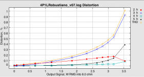
Distortion is as predicted in the simulation (e.g. 0.1% for 1W and about 0.2 - 0.25% for 2W). Just above 2.2W distortion creeps up rapidly given grid current, which is not modelled properly by the 4P1L pentode model:

Looking at distortion versus frequency, it's interesting to compare the BJT performance against the depletion FET. With lower Cob compared to the Coss of the FET, the BJT should be able to drive better the 4P1L. In fact, the BJT is more linear when swinging many volts compared to the depletion FET, so the proof is in the pudding:

The BJT is indeed more linear but if we compare the THD vs frequency of both drivers when providing 2W output power, we can see that the BJT is suffering as much (and even more given poorer slew rate) than the FET at frequencies above 12kHz. Also FET's THD versus frequency is more linear up to 10kHz, whereas the BJT has a peak around 6kHz and a dip closer to 10-11kHz. Either way, the BJT outperforms the FET in overall THD up to 11kHz.
I need to listen to this circuit now...
I'm inclined to think that higher collector current (or a buffer/follower) between the BJT and the 4P1L should be a good way of reducing the distortion at high frequency...
Ale
Here is my quick breadboard with components I had at hand, so there is a slight variation from the simulation:
The Q1 is obviously an MPSA42. C3 was substituted with a 10uF/25V electrolytic (yes you read well). Rf is a 250k carbon pot and R2 is built of a series of 1K pair in parallel plus 100 ohms in parallel, four resistors are wire-wound 1W. C1 is actually a 30uF/450V ASC Oil cap.
I haven't measured the collector current but it seems to be around 1.3-18mA. Variance is due to tolerance of RE and R3. I need to measure the actual resistance of Rf but is somewhere between 180 and 200K.
As Rod suggested, the circuit is very stable and easy to dial the right feedback with the potentiometer. The 4P1L is biased about -9V and is slightly under the max Pa in this case.
Distortion is as predicted in the simulation (e.g. 0.1% for 1W and about 0.2 - 0.25% for 2W). Just above 2.2W distortion creeps up rapidly given grid current, which is not modelled properly by the 4P1L pentode model:
Looking at distortion versus frequency, it's interesting to compare the BJT performance against the depletion FET. With lower Cob compared to the Coss of the FET, the BJT should be able to drive better the 4P1L. In fact, the BJT is more linear when swinging many volts compared to the depletion FET, so the proof is in the pudding:
The BJT is indeed more linear but if we compare the THD vs frequency of both drivers when providing 2W output power, we can see that the BJT is suffering as much (and even more given poorer slew rate) than the FET at frequencies above 12kHz. Also FET's THD versus frequency is more linear up to 10kHz, whereas the BJT has a peak around 6kHz and a dip closer to 10-11kHz. Either way, the BJT outperforms the FET in overall THD up to 11kHz.
I need to listen to this circuit now...
I'm inclined to think that higher collector current (or a buffer/follower) between the BJT and the 4P1L should be a good way of reducing the distortion at high frequency...
Ale
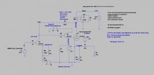
Hi Ale,
Splendid, it's coming along.
If the grid is drawing current, altering the resistors and Ic is unlikely to overcome the load problems faced by the driver. So a follower stage will work better, and may allow a little positive grid excursion, and a little more output power.
MPSA42 is again used, for low input capacitance this time: 40pF or less. A ZVN0545 MOS FET may work well too.
Beware though - may need to limit the grid current with a stopper, to avoid breaking the follower MPSA42.
Here's an example.
C4 is added to show that it can withstand high capacitive loads without failing.
The follower must be supplied with 70-100V to avoid breaching the Safe Operating Area of an MPSA42. A resistor divider + FET follower is easiest.
An MJ350 for the follower could be used, but that will probably load the driver too much with capacitance or base current.
Attachments
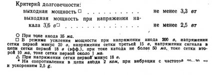
Interestingly, the 4P1L data gives an operating regime with 3.3W output, judges as the minimum available power after rated lifetime of 1000 hours :
Regime:
Va= 200V; Vg3 = 15V; Vg1 = -20V [Vg2 not given]
Ik = 50mA max; Ig2 = 10mA; Ig1 = about 1mA
Could easily set Vg2 to satisfy the 10mA condition.
The data also gives a "Maximum oscillatory Power, at wavelength of 10m" as "about 4,5W".
With these is mind, we should probably aim for more power from Señor Robustiano!
To achieve it will require some more changes, though:
- higher voltage supply for 2nd grid, with sharp cut-off current limiter;
- replace cathode resistor with stabilised negative bias regime.
These can easily be added later, if the current design shows some definite promise of sound-quality.
Attachments

Brilliant ideas Rod! I will try the attached, thoughts?
Do you think a 100ohm stopper should be added to the 4P1L grid?
I think I should dial the feedback to get a more triode-like harmonic profile...
Interesting findings about the 4P1L's operating point. I wasn't aware of your Russian language skills 🙂
I could try lowering the anode voltage and readjusting the feedback network. The screen bias should be a follower with current limiter using a BJT?
Cheers
Ale
Attachments
Ale, is it possible setting where 3H is not so strongly pronounced in the entire power range?
I'm not sure that is so extremely dominant 3H meet auditory tastes.
I'm not sure that is so extremely dominant 3H meet auditory tastes.
Hi Rajko,
Absolutely and thanks for raising the point. I meant as well this on my post above.
By dialling the Rf you can get the H2 closer to H3 levels. Of course when grid current kicks in near A2 you will get H3 and H5 raising exponentially.
I think in practice it may be easier to make R3 (non-degenerated Re) variable (i.e. trimpot) and also adjustable the negative supply so you can tweak the feedback level whilst running an FFT.
Attachments

Ale, the circuit looks good.
LND150 needs to give near to 2mA to give best performance, please take care.
Yes, 100R stopper will do for starters... I'll do a screen circuit when I get a minute.
The apparently high H3 condition is probably when the H2 & 4 in the driver is effectively cancelled in the pentode stage. Tune it by ear, when the meter gets it near to where you like it.
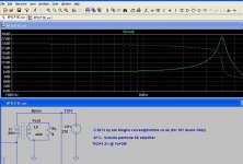
That is because you're using the ideal transformer model. In reality the leakage inductance/capacitance will roll off the HF beyond 100kHz for sure. If you add the 4.3mH Lsp in series with the primary, you will get a -3dB around 250kHz. In practice, I'd expect this much lower frequency as haven't included the interwinding capacitances in the spice circuit 🙂
Yes Ale, you're right.
But I think the anticipated 4.3 mH will not eliminate the peak which ever have on grid G1 of 4P1L.
Thanks euro21.
But I think the anticipated 4.3 mH will not eliminate the peak which ever have on grid G1 of 4P1L.
Thanks euro21.
After a few year of distraction, now I am getting back to this hobby.
4P1L is one of my favorites. I also built a 4P1L headphone amp several years ago, the detail is here at
- 7N7 4P1L Headphone Amp - Yaqin M12B Mod -
I have been thinking about further changes to the amp. Some schema changes and simulation have been done earlier, but have never been implemented. I will need to go find the files in my computer.
I usually use this transformer (OPT, interstage) model.
Great stuff Euro21, will look into this. I've been deriving transformer parameters with Morgan Jones' method but not for the LL1623 yet
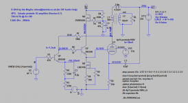
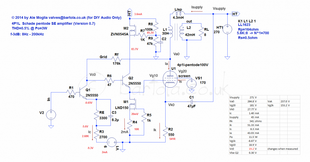
Hacked a simple PCB to build the follower to drive the 4P1L as suggested by Rod. I had to play with the LND150 setting resistor (R4) to achieve the 2mA of idle current. I ended up biasing the 4P1L rather hot at about 11.5W which exceeds the specs. The Q2 VBE was not possible to measure as the Q2 would oscillate I guess when I place the tester lead on Q1 collector and the voltage seems to drop when I try to measure it. Should have added a ferrite bead:
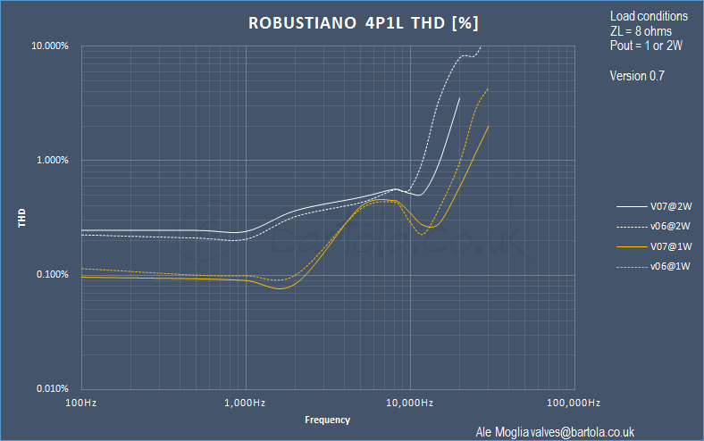
When measuring distortion against frequency, I was surprised to see that the follower provided some impact in reducing the HF distortion. For example at 20kHz, THD reduced from 0.96% to 0.59% @1W output power and from 7.84% to 3.52%:
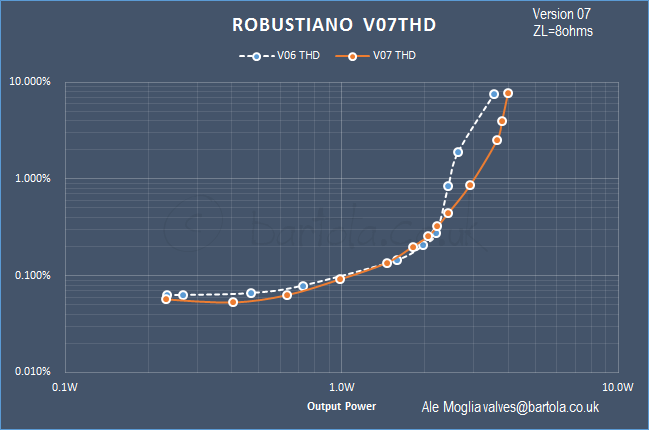
What is nice to see now is the effect of the follower providing sufficient source current to the 4P1L grid. Above 2.5W, the grid current kicks in and we can see how "Robustiano" can deliver 3W at less than 1% until starts to clip about 3.5W:
I found that if I were to reduce the Rf further and therefore increasing the collector current but obviously exceeding the 4P1L power dissipation too much as collector current was about 45-48mA, the distortion at 20kHz falls significantly. I suspect I should increase the collector current to enable better drive of Q2 due to its Cib (30pF). To keep the current feedback arrangement this could be done by reducing the negative emitter voltage source (V1). Should try this I guess...
When measuring distortion against frequency, I was surprised to see that the follower provided some impact in reducing the HF distortion. For example at 20kHz, THD reduced from 0.96% to 0.59% @1W output power and from 7.84% to 3.52%:
What is nice to see now is the effect of the follower providing sufficient source current to the 4P1L grid. Above 2.5W, the grid current kicks in and we can see how "Robustiano" can deliver 3W at less than 1% until starts to clip about 3.5W:
I found that if I were to reduce the Rf further and therefore increasing the collector current but obviously exceeding the 4P1L power dissipation too much as collector current was about 45-48mA, the distortion at 20kHz falls significantly. I suspect I should increase the collector current to enable better drive of Q2 due to its Cib (30pF). To keep the current feedback arrangement this could be done by reducing the negative emitter voltage source (V1). Should try this I guess...
Just did a quick test. I tried increasing (more negative) VEE but distortion was higher, so tried reducing the VEE rather than increased and noticed that -8V produced much lower distortion at HF (about 1% at 30kHz). How come this 1V difference can produce such a difference?
If the dc operating point was changed, it might have a strong effect.
going from-9V to -8V will decrease the Ic at idle. You should be able to get the same effect by increasing the total dc resistance in the emitter RE + R3.
Then, you can vary the ratio of RE:R3 to get the optimal trade-off of gain vs distortion (or minimal distortion if you don't care about gain).
going from-9V to -8V will decrease the Ic at idle. You should be able to get the same effect by increasing the total dc resistance in the emitter RE + R3.
Then, you can vary the ratio of RE:R3 to get the optimal trade-off of gain vs distortion (or minimal distortion if you don't care about gain).
Thanks Rod. Can you please explain me why decreasing collector current will reduce distortion at HF? I'd have bet that by increasing collector current would have helped in driving the input capacitance of the follower. What am I missing here?
I think from what you're saying is that is better to increase the total emitter DC resistance and therefore keeping the VEE at -9V from a stability point of view.
I think from what you're saying is that is better to increase the total emitter DC resistance and therefore keeping the VEE at -9V from a stability point of view.
Yes, the negative voltage needs to be at least 3 or 4x the value of the negative peak.
So you should be able to stick to one value of neg supply, and vary the 3 resistors: Rc, Re and R3 to configure the whole capability of the gain stage.
There are several things at work here. If you change Rc, then the total (RE + R3) must be restored to the same proportion of Rc, to keep the collector voltage at the desired level (to give the correct anode-current in 4P1L.
Increasing the value of R3 (unbypassed by the cap) will decrease gain, and decrease distortion.
Next you are balancing two distortions: in the driver, and in the 4P1L. the driver NPN only requires 100uA for good performance on its own, and will distort more for muchhigh current (because of increased base current in signal excursions). But this is balanced against the demands of the load (4P1L input).
Also, you can see from the test yesterday, that driver and 4P1L distortion (2H, 4H) can cancel for some idle current values - so you have to look at the division of harmonics.
But with all the resistor changes, please check that the dc operating point is unchanged - unless you want to experiment with that, too!
- Home
- Amplifiers
- Tubes / Valves
- One more 4P1L SE