Run a LED to get some voltage, connect it to the input's 47K resistor (in place of ground).
The output slope (V/I) will need to be examined for suitability, but that's true of any device.
Cob of MPSA42 is <5pF with some good voltage across it.
The output slope (V/I) will need to be examined for suitability, but that's true of any device.
Cob of MPSA42 is <5pF with some good voltage across it.
Ok an CCS feeding the LED biasing the 47k base resistor. Will you do the emitter with a degeneration emitter resistor as well?
hey guys, i did not read the entire thread but i have a question...
so far circuits posted here seems to show fixed biasing,
any reason cathode biasing can not be used with this tube? just like in a 2A3?
i was thinking biasing two parallel 4P1L's at say 250 volts and 60mA,
your thoughts please.....
so far circuits posted here seems to show fixed biasing,
any reason cathode biasing can not be used with this tube? just like in a 2A3?
i was thinking biasing two parallel 4P1L's at say 250 volts and 60mA,
your thoughts please.....
Ok an CCS feeding the LED biasing the 47k base resistor. Will you do the emitter with a degeneration emitter resistor as well?
Yes, emitter resistor needed, primarily to set the (eg 1mA) idle current in the transistor stage.
BJT wll work with reasonable gm even below 1mA.
If the input impedance is not high enough for your design, you can use darlington-connected MPSA42s.
hey guys, i did not read the entire thread but i have a question...
so far circuits posted here seems to show fixed biasing,
any reason cathode biasing can not be used with this tube? just like in a 2A3?
i was thinking biasing two parallel 4P1L's at say 250 volts and 60mA,
your thoughts please.....
Cathode biasing works fine, so long as you can accept the sound of the bypass capacitor.
But many builders use them with Filament Bias (cathode resistor - but which carries the filament current as well as the anode current). This allows the value of the cathode resistor to be low enough that a bypass capacitor is not needed. The filament current must be extra-quiet, so purpose-built regulators, like my kits, are used.
For bipolar input, you may want to look at Kamijo-san's work as shown here and replace the zener with LED and adjust biasing accordingly. A low noise npn with hfe >200 is recommended.. . . How will you suggest biasing the common emitter stage?
For the simpler JFET circuit, a lot more work is actually required. Idss matching is mandatory. If you plan to bias at 5mA, a ~6mA Idss high-GR or low-BL grade 2SK170 are preferable to arrive at minimum source resistance. Maybe even omit the source degeneration altogether if you have low level source.
You may even want to read the first few pages of the JFET BOZ thread at Pass Forum to get a bit more feel. So, why choose the complicated way? It is difficult to justify on technical merit. Better build, listen and decide. In your case, maybe you can share a little better light in technical terms afterwards.
Thanks Indra!
Regarding the bipolar circuit, will you suggest the addition of the pot to trim the bias voltage at the base as suggested in the link? I guess that can help me to set up the bias point and therefore the feedback without varying the feedback resistor?
Regarding the low signal JFET option using the 2SK170. I read the first 8 pages of the Nelson Pass thread and when I found Nelson's post regarding the FET's THD performance started to question myself whether the JFET can handle the voltage swing required here without significant distortion. If I remember well, I think I measured 4Vpp swing at the DN2540 drain to produce the 2W output.
Ale
hey guys, i did not read the entire thread but i have a question...
so far circuits posted here seems to show fixed biasing,
any reason cathode biasing can not be used with this tube? just like in a 2A3?
i was thinking biasing two parallel 4P1L's at say 250 volts and 60mA,
your thoughts please.....
4P1L is probably one of the few valves that can be run easily with filament bias. As Rod said, this has an advantage if you want to avoid the cathode capacitor. I prefer the sound of this, as many other builders around here. I also tried fixed bias and now am experimenting with a cathode bias circuit again (with ultra-path bypass this time). There is no reason you can use it this way.
As with every DHT amp, you will have to pay significant attention to the filament circuit and avoid AC or poor regulated DC implementations for ultimate performance. You will get worse hum, noise or intermodulation products of traditional regulators which are not fit for purpose for this task. Rod has a regulator boards that are superb for this task. Many of DIYers are using them successfully for DHT preamps and amplifiers.
Ale
my experience with the 2A3 is such that in the two amps i built, hum was
not audible, you have to put your ears really close to the speakers to hear
only faint hum...so i wonder if anybody tried ac heating and what was the
result...
yes, ultrapath could be a nice way to do it, i am building one right now
and will certainly give it a try....
not audible, you have to put your ears really close to the speakers to hear
only faint hum...so i wonder if anybody tried ac heating and what was the
result...
yes, ultrapath could be a nice way to do it, i am building one right now
and will certainly give it a try....
I recommend you to read this when you get the chance:
http://www.bartola.co.uk/valves/why-filament-regulators-in-dht/
http://www.bartola.co.uk/valves/why-filament-regulators-in-dht/
The pot, especially the 10 turn variety, is "the" tool during breadboarding. But once the satisfactory OP is found, I usually replace with fixed resistor, usually 2-3 resistor in series/parallel combination. More choice, no moving parts and less susceptible to problems and degradation.. . .will you suggest the addition of the pot to trim the bias voltage at the base as suggested in the link? I guess that can help me to set up the bias point and therefore the feedback without varying the feedback resistor? . . .
Maybe you haven't seen this remark. There are ways to answer your need. One of them is the BF862 variation of the concept by Juma.. . . whether the JFET can handle the voltage swing required here without significant distortion. If I remember well, I think I measured 4Vpp swing at the DN2540 drain to produce the 2W output.
For bipolar input, you may want to look at Kamijo-san's work as shown here and replace the zener with LED and adjust biasing accordingly. A low noise npn with hfe >200 is recommended.
<cut>
Yes, you can use that circuit, and a 6.2V zener will be low enough noise, if you put a film cap across the trimmer.
But this design derives power from the cathode of the power tube. CCS from the power supply will be even better, if you have another depletion FET handy (use the one removed from the current design!). Run 2-6mA into the zener, and check for minimum noise.
With a 6.2V zener, use a 5.6K emitter resistor, and get 1mA in the transistor's collector. input impedance will then be 400-600K+ depending on the transistor type (Hfe at 1mA).
I recommend you to read this when you get the chance:
Why filament regulators in DHT? | Bartola Valves
thank you...i will read it...
With a JFET, using a source resistor (must be unbypassed though) will allow wider swings before heavy distortion sets in. Or, a negative bias voltage can be combined with a source resistor for more flexible biasing.
But - the BF862 is really best where small signals are to be amplified with low noise. It has a breakdown voltage of only 20V, also.
Among the easy-to-get JFETs, a J111 would be more suitable, since its breakdown voltage is 35V, and it should be able to run 1-3mA with -2V of bias
But - the BF862 is really best where small signals are to be amplified with low noise. It has a breakdown voltage of only 20V, also.
Among the easy-to-get JFETs, a J111 would be more suitable, since its breakdown voltage is 35V, and it should be able to run 1-3mA with -2V of bias
Other precautions when using JFETs:
The zener (27V) will certainly be needed - they are much more fragile than say, MPSA42.
Also, the sample-to-sample variations of JFETs are so large, that for stable bias you'll need adjustable negative bias and a source resistor, or buy 100 JFETs and match a few up.
Since the operating voltage of the transistor in this position needs 10-20V across it, beware running a JFET with Vds above a few volts, and more than 0.5-1mA. If you do, you may get trouble with Igsx - excess gate current! Check out the data sheet before setting the bias. More than say, 100pA of Igsx can lead to noise problems, and even bias stability trouble.
For instance: the BF862 with 1mA flowing shows Igs of <10pA at 5V Vds. At 15V, it increases over 10^4 times to 200nA. At 10mA and 15V it exceeds 1uA. This is input current, and noisy with it.
Totally with you on this one Rod. However, with all the difficulties and shortcomings mentioned, it really is rather astonishing that so many of us prefers JFETs' signature over bipolars' on input duty. I pick JFET simply from subjective listening preference, sounds less metallic without loss of detail. I normally listen on low level to simple music, perhaps low higher order component of harmonic distortion is main reason. Care to share an opinion?Other precautions when using JFETs . . .
Hi Indra,
Yes, it can be done for sure. I wanted to mention some of the things that need to be carefully considered - or the JFETs don't get a proper chance to show what they can do.
I use the JFET 2SK369 for input duty, in my Moving Coil amplifier, and I think that it is the best solution - especially in Shunt Cascode connexion.
Yes, with JFETs, correctly biased and configured for low gate current, the noise will be low, and the higher-order harmonics absent.
But for higher signal voltage, I use triodes, also in Shunt Cascode.
I can echo what Rod said about the shunt cascode sound using JFET. I also implemented it and love the sound of the RIAA stage.
Thanks both for the great input, I'm learning a lot with this experiment.
So here are the 3 options to test:
1) Option 1: HV depletion FET using DN2540/LND150
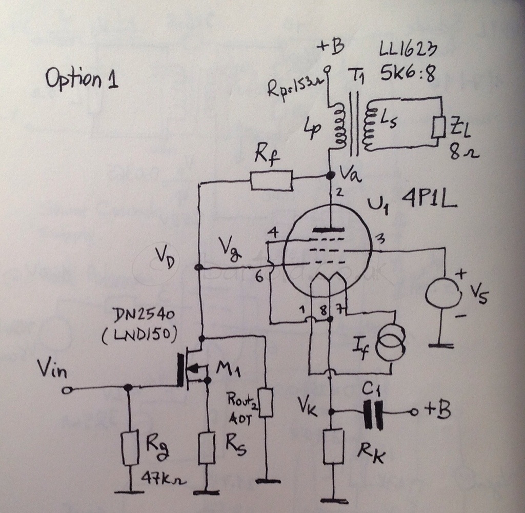
Disadvantages: may be difficult to calibrate given FET variance of parameters. Also output capacitance proved to be increasing distortion at HF. Challenge is to test with better OP and higher Id to increase slew rate. Also may need a shunt resistor to achieve the FB level desired.
Advantages: I like sound of depletion FETs. Simple circuit and no additional power supply.
2) Option 2: Bipolar common emitter driver
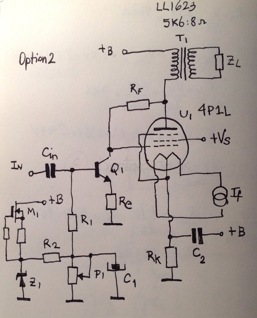
Disadvantages: bipolar sound? Needs an additional supply for bias and also an input capacitor.
Advantages: easier to calibrate due to parameter consistency and tolerance. Lower output capacitance to improve HF response
3) Option 3: JFET input using LSK170, BF862, etc.
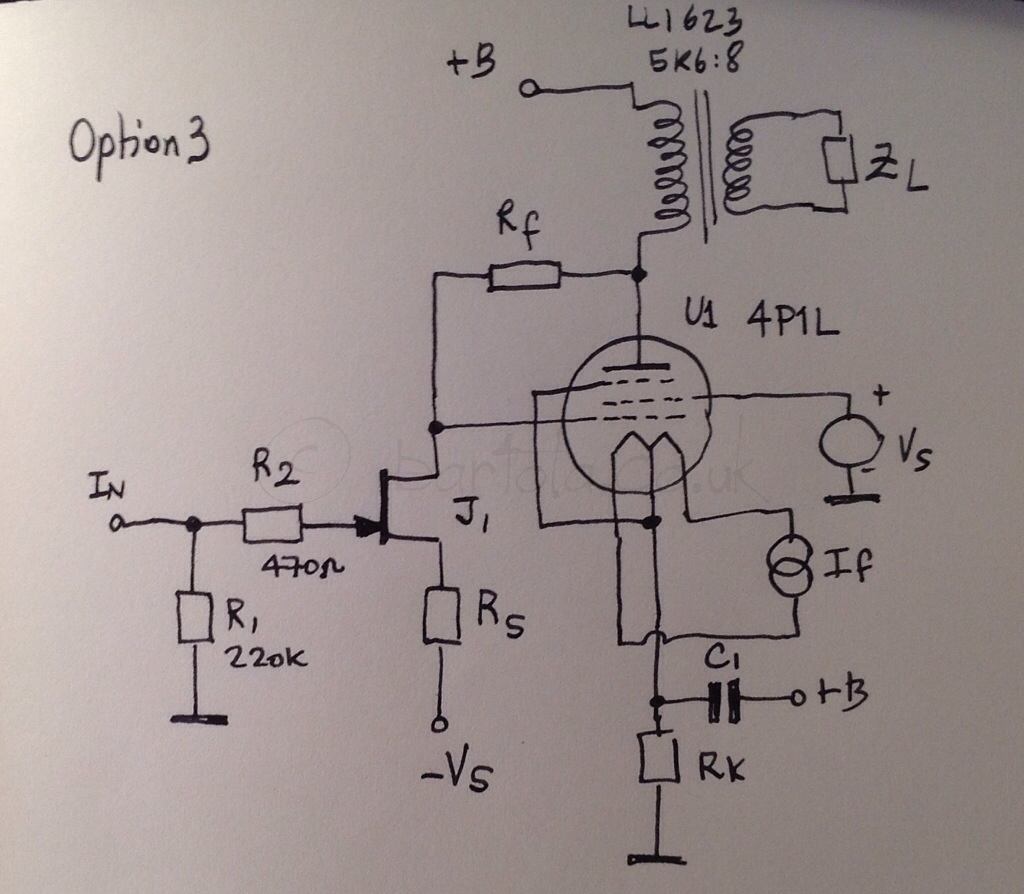
Disadvantages: jFET distortion at higher signal levels. Additional bias supply required for source. Difficult to calibrate given FET variance of parameters.
Advantages: jFET sound. Low output capacitance to improve HF response. No additional input capacitor required.
Did I get these right?
Cheers
Ale
Thanks both for the great input, I'm learning a lot with this experiment.
So here are the 3 options to test:
1) Option 1: HV depletion FET using DN2540/LND150
Disadvantages: may be difficult to calibrate given FET variance of parameters. Also output capacitance proved to be increasing distortion at HF. Challenge is to test with better OP and higher Id to increase slew rate. Also may need a shunt resistor to achieve the FB level desired.
Advantages: I like sound of depletion FETs. Simple circuit and no additional power supply.
2) Option 2: Bipolar common emitter driver
Disadvantages: bipolar sound? Needs an additional supply for bias and also an input capacitor.
Advantages: easier to calibrate due to parameter consistency and tolerance. Lower output capacitance to improve HF response
3) Option 3: JFET input using LSK170, BF862, etc.
Disadvantages: jFET distortion at higher signal levels. Additional bias supply required for source. Difficult to calibrate given FET variance of parameters.
Advantages: jFET sound. Low output capacitance to improve HF response. No additional input capacitor required.
Did I get these right?
Cheers
Ale
You got it Ale. And yes, simple ckt is the place to sharpen the feel.
Some notes you may consider :
We match semiconductors for simple gain circuits with little or no loop feedback due to device variance. Idss and Vp on JFETs, hfe and Vbe on bipolars and Vgsth and Gm on MOSFETs. Otherwise we are forced to operate the device away from the sweet spot or use more feedback.
I may repeat things you already know but just in case. The Y(ellow), GR(een), BL(ue), V(iolet) suffix are used by many japanese manufacturers to grade their bipolars on hfe and FETs on Idss, details usually found at the bottom of the first page of the datasheet. European manufacturers prefer A, B, C, D, E suffix. While Fairchild prefer to just put different part number like J111, J112, J113. Not so sure on others.
On option 1, the need to raise Id is to find a more linear OP. Main problem is low Gm (slope of transfer characteristics) that varies nonlinearly with Id at low Id value.
On option 2, when filament bias is used, current diodes or cascoded JFET CCS feeding the zener or LED can be supplied from the gyrator (+) end of your filament regulator. Hfe matching is not mandatory but improves imaging and separation.
On option 3, if an input coupling cap and biasing network similar to option 2 is retained on breadboarding phase, no additional supply is required. You may pursue further improvements if the "JFET sound" justify more efforts.
- Home
- Amplifiers
- Tubes / Valves
- One more 4P1L SE