
with 500mV, 600mV or 1V measured on 2V range I do not have any input saturation issues.
These issues appear, say, when input voltage approaches .99% of the scale.
The inputs are 1MOhm.
I can repeat with many more types of 317, old and new: ST, F, S, ON, etc
I fully believe you tested up to 5-6V. No clue then.
We can wait until someone repeats the experiment. Or we can also try to link this THD problem with the big apparent noise at <10mV signals.
Maybe I need to play a bit with the Zobel capacitor? You know the 317 much more better than me. Can you recommend more subtle tricks or brute force?
Should I use a foil Cap? Not sure what kind of Keramics I have.
according to DS of 4262, the Output impedance of Source is 600Ohm. Could that be the issue combined with this circuit?
I don't think that 600 ohm could disrupt the operation; anyway, I'll try to add a 560ohm in series with the 50ohm of the generator, but I have little hope.
I can also plug another 317 to see whether it makes any difference, but there too I have little hope: if a dirt-cheap generic chip works perfectly, I see no reason for a ST or Onsemi to fail.
Something you can try is to take the analyser input from the input of the circuit (still connected) instead of the output: this will show if the 317 injects perturbations into the signal (due to the 600ohm or anything else).
You can also check the DC voltages on the input and output (leaving the coupling caps out, obviously). You should see Vcc/2 on the input and Vcc/2 + 1.25 on the output.
If a coupling cap is leaky, it could upset the DC bias point
OK, I made the tests:
-610ohm input: no change
-317 ST: identical
-317 Onsemi: identical
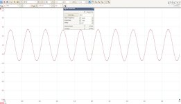
In all cases, the clipping begins at 11Vpp
-610ohm input: no change
-317 ST: identical
-317 Onsemi: identical
In all cases, the clipping begins at 11Vpp
I am embarrased.
Faulty point found: my instrument (the 4262) is upset with Source above 500mV and if I connect it to the DUT via a probe.
No clue. I am using it almost daily, but with source connected via BNC-BNC cables and it runs fully ok.
Maybe the output does not like something in the Probe(s) themselves. I tested bot the originals and a Tektronics one. Same issue.
more precisely, because the source was connected ALSO to a unpowered machine (the buffer which I trying to do).
So, I guess what we see was the unpowered Si-junctions being AC/RMS biased... clipping above ca. 550mV 🙂
I disconnected the cables and now it looks normal.
New Plots are coming 🙂
So, I guess what we see was the unpowered Si-junctions being AC/RMS biased... clipping above ca. 550mV 🙂
I disconnected the cables and now it looks normal.
New Plots are coming 🙂
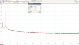
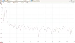
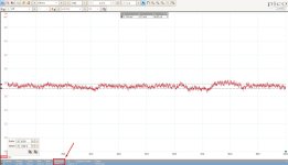
more plots, if anyone wants to have fun and compute SNR more precisely.
From 1ms waveform I selected a zone with ca. 5-8KHz noise: the RMS there is ca. 23uV.
Not exactly good for 25mV follower role, but surely absolutely impressive for a 0dBu (+14dB margin) Line Buffer + Headphone derivation in the format of 1-BJT real estate.
Many Thanks to LV and Marcel!
From 1ms waveform I selected a zone with ca. 5-8KHz noise: the RMS there is ca. 23uV.
Not exactly good for 25mV follower role, but surely absolutely impressive for a 0dBu (+14dB margin) Line Buffer + Headphone derivation in the format of 1-BJT real estate.
Many Thanks to LV and Marcel!
Attachments
-
 RemeasureClean_LM317T_7mV_128PTS_Averaged.jpg179.8 KB · Views: 53
 -
 RemeasureClean_LM317T_7mV_128PTS_NotAveraged.jpg190 KB · Views: 50
 -
 RemeasureClean_LM317T_ShortedInput_Time_100ms_ALP200KHz_DLP20KHz.jpg225.6 KB · Views: 49
 -
 RemeasureClean_LM317T_ShortedInput_Time_1ms_ALP200KHz_DLP20KHz.jpg255.1 KB · Views: 57
Good, at last.I disconnected the cables and now it looks normal.
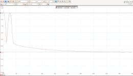
Regarding the PSRR, I didn't measure anything, and this is the simulated result:
Rather underwhelming, but it is mainly caused by R1, injecting a signal into C2. R1 should be split and bypassed if you need a good PSRR. I'll measure the actual PSRR tomorrow
The PSRR will need a filter on the bias. ie split R1 into two resistors and filter capacitor. Or, you could use a bipolar power supply.one more question: what is the PSRR of this circuit?
It would be simpler to use an op-amp instead of a LM317, and better performance as well. After all, a LM317 is an ~op-amp and a (noisy) voltage reference.
A CFP is variation on the "White buffer".
LV's "tandem" circuit uses regenerative bias to cancel the distortion of an EF buffer. LV also posted some inverting amps with diode distortion cancelation.
I simulated a dozen buffer circuits and nothing outperformed a complimentary EF pair.
You can bootstrap the bias for a higher input impedance, but it exaggerates the 2nd order harmonics, which may be a good thing. It makes a great electric guitar input circuit.
This will follow. Thanks as well!The PSRR will need a filter on the bias. ie split R1 into two resistors and filter capacitor.
OpAmp versions: I know, I agree but Not a follow. Here is about repurposing an old board, striping out old over-enginneered parts and replace with simpler BJT-like topologies (those which fit the PCB - hence the topic!) which will still satisfy the old specs. The remaining PCB real estate, now free and unused, I want to repurpose it to more cool features. In this case, I wanted to make a mixer/follower. Generally this is my drive, and is not something like reaching for the furthest stars. A 96dB or better SNR is already the theoretical CD quality.
Sorry, I am cold on this.A CFP is variation on the "White buffer".
LV's "tandem" circuit uses regenerative bias to cancel the distortion of an EF buffer. LV also posted some inverting amps with diode distortion cancelation.
I simulated a dozen buffer circuits and nothing outperformed a complimentary EF pair.
You can bootstrap the bias for a higher input impedance, but it exaggerates the 2nd order harmonics, which may be a good thing. It makes a great electric guitar input circuit.
Please PM me to learn what the "CFP", "White buffer", "LV's tandem", "regenerative bias", "diode distortion cancellation" ideas are.
Which topology of the complementary EF pair?
"Boostrap the bias": this sounds as a really cool option to have - as as switch (normal vs. bootstrapped) to be able to change the tonality of the mixer. I am one of the H2 lovers. Can you please share the idea (in PM probably)?. Or here, if you feel like so is better.
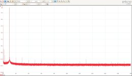
After 1h of working ('warming up') the waveform's noise rms in 20KHz has reduced to 7uV average and 10.9uV peak (in 3sec). Longer than this I cannot do, as the DC shifts and nulls the measurement. Pretty cool.
A voltage regulator like the 317 is probably one of the very few options available to replace a common collector almost transparently.
All of the others will require additional nodes to be implemented (but they have advantages of their own).
The 317 has almost ideal properties in this role -except for noise-.
For line-level applications, the noise might be acceptable: to check for it, a listening test is probably your best option.
I can provide (and test) a schematic having all the bells and whistles possible, but it will require additional nodes on the PCB.
The poor LF PSRR of the 317 is in fact exactly the same as for the transistor follower. If you need a good PSRR, you will need to use the same kind of remedy, be it common collector or 317
Sure, please do.I can provide (and test) a schematic having all the bells and whistles possible, but it will require additional nodes on the PCB.
I might have released&unused nodes after all. Justin Case (not a relative of Justin Time).
Listening test will happen soon.
I have measured the PSRR in reality (on the ST sample, but I don't think it matters much).
I have left the bias on the regular 18V supply, and connected the test amplifier to the 317 only. The signal was 4Vpp riding on 18V.
At 100Hz, the PSRR was 86.6dB and at 1kHz 88dB.
These figures are quite good, probably better than those from the datasheet.
I have left the bias out, because it can be filtered as much as one wants, like this for example:

This is the bootstrapped version, to increase the input impedance:

It brings the impedance to ~3 megohm, except at 1 kHz where it rises to 300M, due an unfortunate choice of values in the example.
Also note that the 317 is certainly not the only one usable as a buffer: more modern, higher performance regulators exist, and some have a very low noise compared to the 317.
The scheme needs to be tested in reality, because aspects like stability are poorly handled in simulations
I have left the bias on the regular 18V supply, and connected the test amplifier to the 317 only. The signal was 4Vpp riding on 18V.
At 100Hz, the PSRR was 86.6dB and at 1kHz 88dB.
These figures are quite good, probably better than those from the datasheet.
I have left the bias out, because it can be filtered as much as one wants, like this for example:
This is the bootstrapped version, to increase the input impedance:
It brings the impedance to ~3 megohm, except at 1 kHz where it rises to 300M, due an unfortunate choice of values in the example.
Also note that the 317 is certainly not the only one usable as a buffer: more modern, higher performance regulators exist, and some have a very low noise compared to the 317.
The scheme needs to be tested in reality, because aspects like stability are poorly handled in simulations
Last edited:
Thanks LV!
One question, the resonances which are apparent (100Hz for PSRR, 1KHz for Z_in): how they come about?
Are they specific to 317? Or to 317+circuit values? Or common collector topology ? I don't know (yet) how to simulate your results at my end, but will these resonances exist also with BJT?
Care to share the LTSpice project, to save some good chunck of my time?
I do resonances all day, by profession, and I learned generally to try to avoid any unnecessary ones. Especially when I need a large bandwidth solution.
- Home
- Source & Line
- Analog Line Level
- One BJT line amp/buffer