Perry, if you see this, I once again started working on the the Orion HCCA 225 Digital Reference that you were helping with before... the thread "Again needing help fixing Orion HCCA Digital Reference". I found the circuit board itself had continuity from the capacitors having leaked electrolyte, which was what was causing the problem with the muting circuit.
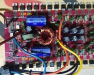
I recently acquired another circuit board for it. The transformer and few of the power Mosfet's were blown on it. I replaced the transformer with the one from my board, also some resistors, diodes, ceramic capacitors, etc... I also replaced all the electrolytic capacitors, power Mosfet's and output Mosfet's using new parts. So...I then put power to the amp and it powers up. I shut it down connect the RCA's and one speaker. It works great. I shut it down and connected the another speaker to the other channel. It still works great. I let it play for a bit. Shut it down and do a visual inspection of the board...all looks good. So I power it back up again but this time it takes a few seconds to power up (red light to come on). I shut it down and powered it back up and it immediately comes on. I then shut it down, waited a few minutes and powered it back up and it again takes a few seconds to power up. So at this point I shut it down, waited about 10 minutes and then tried to power it back up but now it no longer powers up at all. I checked the center legs of the power Mosfet's and they do have 12 volts. Nothing on the other legs. Also noticed the center legs on both sides of the board are +12 volts... Any ideas on what I should check?
I recently acquired another circuit board for it. The transformer and few of the power Mosfet's were blown on it. I replaced the transformer with the one from my board, also some resistors, diodes, ceramic capacitors, etc... I also replaced all the electrolytic capacitors, power Mosfet's and output Mosfet's using new parts. So...I then put power to the amp and it powers up. I shut it down connect the RCA's and one speaker. It works great. I shut it down and connected the another speaker to the other channel. It still works great. I let it play for a bit. Shut it down and do a visual inspection of the board...all looks good. So I power it back up again but this time it takes a few seconds to power up (red light to come on). I shut it down and powered it back up and it immediately comes on. I then shut it down, waited a few minutes and powered it back up and it again takes a few seconds to power up. So at this point I shut it down, waited about 10 minutes and then tried to power it back up but now it no longer powers up at all. I checked the center legs of the power Mosfet's and they do have 12 volts. Nothing on the other legs. Also noticed the center legs on both sides of the board are +12 volts... Any ideas on what I should check?
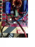
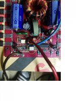
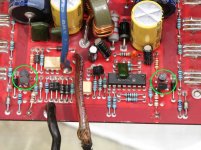
I replaced the opto-coupler with the yellow circle around it from my other board, thinking it may be the problem. I did not replace the other one.
Attachments
Last edited:
I believe I am numbering the pins correctly...
1 - +1.5 volts
2- 0 volts
3- 0 volts - doesn't seem to have any continuity at all
4- +12.08 volts
5- +12.26 volts
6- +12.75 volts
1 - +1.5 volts
2- 0 volts
3- 0 volts - doesn't seem to have any continuity at all
4- +12.08 volts
5- +12.26 volts
6- +12.75 volts
Attachments
Last edited:
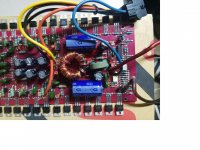
What is the DC voltage on the 3 legs of the MPSA06 in front of pin 4 of the opto-coupler?
What is the DC voltage on both terminals of the thermostat (metallic device under the board)?
What is the DC voltage on both terminals of the thermostat (metallic device under the board)?
MPSA06:
+12.26 volts - leg closest to IC
+12.09 volts - center leg
+11.42 volts - leg furthest from IC
Thermostat:
+11.42 volts on both terminals.
+12.26 volts - leg closest to IC
+12.09 volts - center leg
+11.42 volts - leg furthest from IC
Thermostat:
+11.42 volts on both terminals.
Those are OK. The next thing to check is the voltage on all pins of the 494. Copy and paste the following.
Pin 1:
Pin 2:
Pin 3:
Pin 4:
Pin 5:
Pin 6:
Pin 7:
Pin 8:
Pin 9:
Pin 10:
Pin 11:
Pin 12:
Pin 13:
Pin 14:
Pin 15:
Pin 16:
Pin 1:
Pin 2:
Pin 3:
Pin 4:
Pin 5:
Pin 6:
Pin 7:
Pin 8:
Pin 9:
Pin 10:
Pin 11:
Pin 12:
Pin 13:
Pin 14:
Pin 15:
Pin 16:
Pin 1: +0.002 volts
Pin 2: +0.049 volts
Pin 3: +0.049 volts
Pin 4: +0.71 volts
Pin 5: +1.48 volts
Pin 6: +3.42 volts
Pin 7: -0.00 volts
Pin 8: +11 volts
Pin 9: +3.1 volts
Pin 10: +3.1 volts
Pin 11: +11 volts
Pin 12: +11.42 volts
Pin 13: +4.92 volts
Pin 14: +4.92 volts
Pin 15: +0.050 volts
Pin 16: 0.00 volts
Pin 2: +0.049 volts
Pin 3: +0.049 volts
Pin 4: +0.71 volts
Pin 5: +1.48 volts
Pin 6: +3.42 volts
Pin 7: -0.00 volts
Pin 8: +11 volts
Pin 9: +3.1 volts
Pin 10: +3.1 volts
Pin 11: +11 volts
Pin 12: +11.42 volts
Pin 13: +4.92 volts
Pin 14: +4.92 volts
Pin 15: +0.050 volts
Pin 16: 0.00 volts
Are you sure that it's not producing rail voltage? The IC is producing drive pulses.
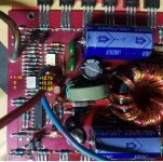
Measure the DC voltage on the power supply FETs, black on leg, red on leg 1. Do they all have the same voltage? If so, what is it? Don't list all if they're not exactly the same.
Measure the DC voltage on the power supply FETs, black on leg, red on leg 1. Do they all have the same voltage? If so, what is it? Don't list all if they're not exactly the same.
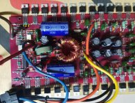
The originals didn't fail but a couple of them had legs that were ready to break.
Leg 3 of the MPSA06 voltages:
Each side front 2: -0.00
Each side back 2: +1.02
Leg 3 of the MPSA06 voltages:
Each side front 2: -0.00
Each side back 2: +1.02
- Status
- Not open for further replies.
- Home
- General Interest
- Car Audio
- Once again need help fixing Orion HCCA 225 Digital Reference