I don't understand. There is only one MPSA06 on each side.
Let's try it this way. Left and right side. Leg 3 of the MPSA06.
Let's try it this way. Left and right side. Leg 3 of the MPSA06.
Yes, you are right. I had a distraction when I was checking them. Leg 3 on the MPSA06's are +1.02 volts on each side. The others where the MPSA56's that were -0.00 volts.
When you say "rectifiers", are you talking about the power Mosfet's? If so, no it didn't produce rail voltage...it was -0.00 volts
The original rectifiers were ECG6240 and ECG6244. I replaced them with NTE6240 and NTE6244. Should I test across legs one and three of those?
Did you measure the voltage with one probe on the tab of one of the rectifiers and the other on the tab of the other rectifier?
That's better. What is the voltage from 1-3 on the PS FETs now?
Do you have an amp meter on your 12v power supply?
Do you have a scope?
Do you have an amp meter on your 12v power supply?
Do you have a scope?
The voltage from 1-3 on the PS FET's is -0.00 volts
I do not have an amp meter on my power supply.
I do have a scope although I am still learning how to use it.
I do not have an amp meter on my power supply.
I do have a scope although I am still learning how to use it.
What do you need to know to use the scope.
Have the voltages you found earlier on the opto, the small transistor, the thermostat and the 494 changed significantly?
Have the voltages you found earlier on the opto, the small transistor, the thermostat and the 494 changed significantly?
Setting the scope to the proper settings for what I'm testing. It is an older model with lots of different settings.
I'll test those later today and get back with you, if that's okay? I need to get a little shut eye for now.
Thanks for your help, Perry.
I'll test those later today and get back with you, if that's okay? I need to get a little shut eye for now.
Thanks for your help, Perry.
Here is what the voltages are now:
Opto:
Pin 1: +1.15
Pin 2: 0.00
Pin 3: 0.00
Pin 4: +12.1
Pin 5: + 12.3
Pin 6: +12.7
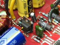
Small transistor (MPSA06 behind opto):
leg 1: +12.3
leg 2: +12.1
leg 3: +11.48
Thermostat:
+ 11.48 on both
494:
Pin 1: +1.9
Pin 2: +1.9
Pin 3: +1.9
Pin 4: +7.0
Pin 5: +1.48
Pin 6: +3.4
Pin 7: -0.00
Pin 8: +11.49
Pin 9: -0.00
Pin 10: -0.00
Pin 11: +11.49
Pin 12: +11.49
Pin 13: +4.92
Pin 14: +4.93
Pin 15: +2.2
Pin 16: -0.00
Opto:
Pin 1: +1.15
Pin 2: 0.00
Pin 3: 0.00
Pin 4: +12.1
Pin 5: + 12.3
Pin 6: +12.7
Small transistor (MPSA06 behind opto):
leg 1: +12.3
leg 2: +12.1
leg 3: +11.48
Thermostat:
+ 11.48 on both
494:
Pin 1: +1.9
Pin 2: +1.9
Pin 3: +1.9
Pin 4: +7.0
Pin 5: +1.48
Pin 6: +3.4
Pin 7: -0.00
Pin 8: +11.49
Pin 9: -0.00
Pin 10: -0.00
Pin 11: +11.49
Pin 12: +11.49
Pin 13: +4.92
Pin 14: +4.93
Pin 15: +2.2
Pin 16: -0.00
From this point, on, if you have 12v on both sides of the thermostat, the voltages on that opto and transistor are OK. You can check them but you don't need to post them.
Pin 4 shouldn't be high. Connect it to pin 7 with a short jumper wire. There could be a bad component so power it up for a few seconds at a time to see if anything in the area gets hot. Also monitor the rail across the rectifiers.
The various, normally heatsink mounted components may get hot as the amp is now.
Just power it up to see if you can get rail voltage.
Connect a jumper wire between pins 4 and 7 on the 494. Pin 4 is high. This will ground it. There are many ground points but pin 4 is sensitive and needs to be connected to pin 7 as the ground point.
The voltage on pins 1-3 also may indicate that there is some leaked electrolyte. I don't, however, understand why it's so different from the first readings.
The voltage on pins 1-3 also may indicate that there is some leaked electrolyte. I don't, however, understand why it's so different from the first readings.
I just put the the transistor you had me previous remove back into place and checked the voltage on pin 4. It dropped back down to +1.2 volts. Again removed it and voltage jumped back up to +7.0 volts.
Going to connect the jumper wire as you instructed now.
Going to connect the jumper wire as you instructed now.
- Status
- Not open for further replies.
- Home
- General Interest
- Car Audio
- Once again need help fixing Orion HCCA 225 Digital Reference