
I modified the other channel. It also had a 9.1 ma 2SK170. I replaced the matching 2SJ74 with one having an Idss of 5.6 (closest I had to a 3 ma difference). After adjustments, I got identical distortion results to the first channel. I am very close to Papa specs at this point. I think the only way to get any closer is to look at selecting laterals. For now, I am going to finish buttoning up the amp and let it play for a while.
If you want to increase it you could always add some more positive current feedback, play with bias points etc.
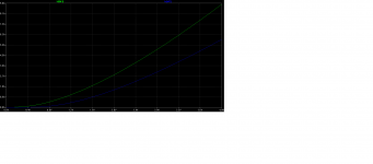
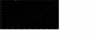
It wasn't 18 percent it was 23 percent higher amplitude on the 20P20. If these mosfets matched the lines would run parallel but they don't. So I bumped the voltage up on the 20P20 and they matched better. Then I raised the amplitude up 23 percent on the f7 circuit and the distortion went down to .005.
Attachments
If you want to increase it you could always add some more positive current feedback, play with bias points etc.
Thanks - I have the positive feedback set for about 100 DF going from 8 Ohms to open circuit. I am using a 15 turn pot for Rpfb - currently set about 20K. Like EVERYTHING in this circuit, everything affects everything else.
 🙂
🙂When I hook it up to some "interesting" speaker loads, I'll try some more tweaks. But for now - thanks for all your help! 😎
Yeah.
Just make it your own.
When Papa designs an amp he still needs to consider the likely range of speakers that could be hooked up to it.
You have the luxury of knowing exactly what speaker will be used.
The best result will come from experimenting with different operating conditions with your specific speakers, not necessarily trying to copy a design exactly that may not provide the best sounding result to your preference.
I made mine with negative output impedance to cancel out the speaker cable influence etc just for fun.
Well the result was pleasing to me. So make the amp yours.
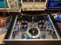
It is done and sounds fantastic! Had to swap 18 Volt trafo for a 20 Volt Antek to get the rails up to 24 Volts DC (too much capacitance on the filter boards 🙂 - 4x 33,000 uF each - have about 4 Amps of ripple current each side) but nice clean DC on the rails @ 1.2 Amp bias each channel. Also losing about 2.4 VAC on the inrush thermistors and about .5 Volt DC on the R in the CRC.
I'll probably continue to tweak the PCF with different speakers and cables.
Anyway - many thanks to Pico for suggestions on the JFETS.
I'll probably continue to tweak the PCF with different speakers and cables.
Anyway - many thanks to Pico for suggestions on the JFETS.
Attachments
Naah
It has a soft start.
But now you've got me intetested to try. Those bloody bastard neighbors.
Hahahaha
It has a soft start.
But now you've got me intetested to try. Those bloody bastard neighbors.
Hahahaha
I am in discussion with Papa about this, I hope he will be able to confirm my results.
It will be good news.
If his parts aren't the same as mine, I will send him my parts to test.
It will be good news.
If his parts aren't the same as mine, I will send him my parts to test.
Transconductance vs Frequency - P Chan Mosfet
Bias is 1A
Vds, 22V, 15V, 6V
No shelving on ECX20P20
Excellent bandwidth.
Lowish Transcoductance
This part is not what I was referring to in my post above, that is a completely different part.
Bias is 1A
Vds, 22V, 15V, 6V
No shelving on ECX20P20
Excellent bandwidth.
Lowish Transcoductance
This part is not what I was referring to in my post above, that is a completely different part.
Attachments
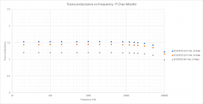
The higher transconductance with higher Vds probably explains why the amp shows lower distortion with higher voltage rails. This seems to have a larger impact than bias. That's the main reason I went with a 20 Volt transformer. Wondering if offsetting the rail voltages would be an interesting experiment?
Hopefully, you can share Papa's insights on the transconductance discussion.
Hopefully, you can share Papa's insights on the transconductance discussion.
Hi Generg
After looking at the posts again I realised Oreo may have got it back to front, and I didn't correct him.
He understood the idea that to compensate for less degeneration you use jfets of different idss values but did it in the completely opposite fashion.
Sorry for not noticing the error or for not correcting it, I was very protective of releasing too many ideas back then publicly.
I can't recall if I just didn't notice Oreo's error or I chose not to correct it.
Either way, positive or negative phase, I am sure his amp still sounds very nice.
In the end it will depend on the parts you have as to what the circuit should be.
I have exicon parts which I suspect are the same as other laterals with regards to their Vgs threshold hold values but I don't know that for a fact.
So the circuit could be different for each person if the laterals are significantly different.
I don't know,my J74 is 3ma higher than my K170 and I can dial in negative phase H2 at 0.05% at 1 watt.Neg. phase H2 shows as a positive value in Ltspice ie: say +85% .My 20 ohm pot is pretty well centered.However this is simmed using Ian Heglun's latest temperature compensated mosfet models and jfet models I have tweaked to reflect Toshiba textbook curves.I know its a lot of simulation as I don't have an actual REW setup (working on it).I don't know what to say other than mine sounds fantastic.Has anyone actually tried what I have and measured the results using a distortion analyzer or that rew software?
I haven't done any REW measurements yet unfortunately either oreo382. I still need to buy a Focusrite and set all of that up. But I can also confirm the 3ma offset between J74 and K170 sounds fantastic. I always come back to this amp as the best sounding of any I've built thus far. That's comparing to the AKSA ALPHA 20W and MoFo. The MoFo has a huge soundstage but the detail and imaging is not even in the same ballpark.
I don't know,my J74 is 3ma higher than my K170 and I can dial in negative phase H2 at 0.05% at 1 watt.Neg. phase H2 shows as a positive value in Ltspice ie: say +85% .My 20 ohm pot is pretty well centered.However this is simmed using Ian Heglun's latest temperature compensated mosfet models and jfet models I have tweaked to reflect Toshiba textbook curves.I know its a lot of simulation as I don't have an actual REW setup (working on it).I don't know what to say other than mine sounds fantastic.Has anyone actually tried what I have and measured the results using a distortion analyzer or that rew software?
Yup - see my post here: On A Hippie Trail, Head Full Of Zombie
That was with an 18-volt transformer, since upgraded to a 20 volt to get more voltage on the rails, so I need to redo the REW measurements. THD should be lower or at least allow me to dial the 3H 10db down from the 2H at .05% THD, 1 Watt, 1KHz sine.
My REW setup is using an old EMU 0404 USB. I am using the differential input to measure across a dummy load (after a pi resistor attenuator) and the internal REW generator. Running it on a Macbook pro.
- Home
- Amplifiers
- Pass Labs
- On A Hippie Trail, Head Full Of Zombie