Low voltage tubes?
A single simpler transformer could be used that would fit all.
And yes, maybe I'm worried a bit of the high voltages and if there is an alternative I would try that.
Is somebody who can help on this?
Thanks!
The PSU pcb could remain, the 6.3V filament supply is OK, only the high voltage part must be adapted for lower voltage, 12 or 24 V.yes it can, but it would need a redesign of the PSU (i would forget using the PS pcb, unless you want to keep the filament supply section) and then as you say, changing values.
if you are worried about the voltage.... read read read, then bite the bullet and do a high voltage project.,
A single simpler transformer could be used that would fit all.
And yes, maybe I'm worried a bit of the high voltages and if there is an alternative I would try that.
Is somebody who can help on this?
Thanks!
Last edited:
The PSU pcb could remain, the 6.3V filament supply is OK, only the high voltage part must be adapted for lower voltage, 12 or 24 V.
A single simpler transformer could be used that would fit all.
And yes, maybe I'm worried a bit of the high voltages and if there is an alternative I would try that.
Is somebody who can help on this?
Thanks!
I had similar aversion and fear towards tube amplifiers.. until I've heard the sound, then all fear went away including my solid state amplifier.🙂
There are low voltage tubes, I know a company using for buffering CD players output. But I don't think you should trade good performance for volts. You need to be methodic and careful as there is a level of danger. First until you are confident work with only one end on HV parts the other keep it in your pocket so if it happens the current does not go from one hand to the other through your heart.
I'll find out anyway if you wish to get used to HV little by little. But this project is mostly all on PCB...


Can I use 180uF/20V Oscons instead 220uf? BOM says 100-220uf
That is Ok!
you can use 100- 220uf max!
Attachments
Last edited:
I do not understand this :
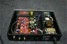
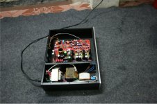
**Where did you get the housing? ***
Can you show me please???
Thank you!
**Where did you get the housing? ***
Can you show me please???
Thank you!
Hi,
i meant:
where did you buy the box / cabinet / case or what ever
the right word is ;-)
Greetings Ulf
i meant:
where did you buy the box / cabinet / case or what ever
the right word is ;-)
Greetings Ulf
Hi,
i meant:
where did you buy the box / cabinet / case or what ever
the right word is ;-)
Greetings Ulf
Oh! now I seen! thank! I buy in the shop in China eshopdiclub.biz
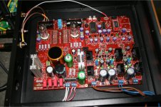
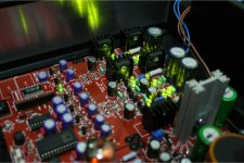
post 524 the salas reg is lit up on the right, yet from the pic no wire from transformer. Have you routed power from another salas reg under the boards?
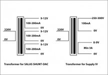
My choise about power supply transformers has been:
LS70-1 0-15X2(0.8A) 0-12X1(0.8A)
R80-55 0-9 X2 (3A),0-250(200mA)
I will test soon.
Have you tested these? Is that 15VAC still ok?
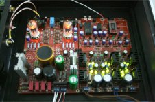
To get the best performance by this DAC project it is necessary use on DAC output module a 200ohm MK132 Caddock resistor.
How accurate that 200R is? Partsconnexion has only 220R.. Any other good sources for those?
RS componentsHow accurate that 200R is? Partsconnexion has only 220R.. Any other good sources for those?
I have these r-core on my table but I am still waitng the pcb to test the these transformers.
The 90% of sound depend by the 200 ohm resistor but are valid also value of 190 - 220 ohm.
If you cannot find the Caddock please use 2 x 390ohm 1% in parallel.
----
I have updated the schematics and the photos on the webpage
DAC End 2 - the AD1865N-K with single ended vacuum output stage
The 90% of sound depend by the 200 ohm resistor but are valid also value of 190 - 220 ohm.
If you cannot find the Caddock please use 2 x 390ohm 1% in parallel.
----
I have updated the schematics and the photos on the webpage
DAC End 2 - the AD1865N-K with single ended vacuum output stage
Thanks! I tried to search 'Caddock' earlier, but MK132 was The Word. 😱RS components
That is Ok!
you can use 100- 220uf max!
I just bought some 270uf on ebay, is that OK?
Is it possible to use a single 12v output from a transformer (at say 2a) and use this to run the entire shunt board?
Or are we better off using individual windings for the AD1865 and a separate one for the CS8414?
Also how critical is the 250v requirement onto the valves?
Could 220-250v be ok? Or is 250v an apsolute must?
Or are we better off using individual windings for the AD1865 and a separate one for the CS8414?
Also how critical is the 250v requirement onto the valves?
Could 220-250v be ok? Or is 250v an apsolute must?
Last edited:
I am going with some Z-foil resistors for the IV. Expensive but hopefully worth it.
I'll report back as i am going to try the, against generic metal film.
I'll report back as i am going to try the, against generic metal film.
post 524 the salas reg is lit up on the right, yet from the pic no wire from transformer. Have you routed power from another salas reg under the boards?
No! You can see in my Tranformer:
Out put:
1. AC=12 V conect to -5V
2.Ac= 12V conect to 2 x +5 v!
Two AC inputs of +5 v I shared a coil, and I must be under the welding
Thanks, thats what i meant by 'shared power'.
your english is WAY better than any of my other languages so thanks for trying with all our questions - much appreciated.
your english is WAY better than any of my other languages so thanks for trying with all our questions - much appreciated.
- Status
- Not open for further replies.
- Home
- More Vendors...
- Quanghao Audio Design
- OLD THREAD DAC End by Andrea Ciuffoli