I think I'm getting mad.
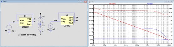
Bias current is resp 3uA and 10uA for both amps, that seems reasonable.
BUT, I measured the input impedance now two times, one with Voltage sources and the other with Current sources.
Outcome should be the exactly same when measuring the input voltage and dividing it by the input current, right ?
Well they are not by a large margin.
See image below.
Hans
The positive input for both opamps sees infinite DC impedance to ground with those current sources, whereas the AC voltage sources are a short to ground at DC so no issue. Since both amps have a PNP and NPN on the input, they might work somewhat even with improper biasing, but obviously not to spec.
@Syn08
Since you mentioned the LM4562 as an exception with a good Spice model, I repeated to measure the input impedance with both a voltage source and also a current source the same way as I did with the LT1395 and LT6202.
Maybe this model works better in Pspice than in LTspice, but outcome is just as strange as with the other two op-amps.
Hans
Attachments
There is something very strange with your sim schematic, I don't think it's LTspice problem.
CLG shows 26dB gain, but tran simulation with 0.2 Vp gives 76Vp at the output????
Damir
That is strange, I never seen something like that even with generic discrete bjt models...
@Syn08
Since you mentioned the LM4562 as an exception with a good Spice model, I repeated to measure the input impedance with both a voltage source and also a current source the same way as I did with the LT1395 and LT6202.
Maybe this model works better in Pspice than in LTspice, but outcome is just as strange as with the other two op-amps.
For the LM4562, being a device level model, I am 100% sure that not having a non inverting input bias current path to the ground will make the device bias incorrectly and hence no input impedance correct results should be expected.
You may want to add a 1G inductance in parallel to the current source and repeat the simulation.
A lot of these models don't simulate power supply current either. In the final analysis the (LTspice) models can only take you so far. Might be a bit better with discrete circuits, but I wouldn't hang my hat on it as any more than 80 or 90% representative of reality. As for 2nd order effects, forget it.
That is strange, I never seen something like that even with generic discrete bjt models...
I did, and the root cause was a severe overshooting and instability that acted even for a sine wave of rather low frequency. If the amplitude of the input sine is small enough, then the issue will dissapear. Try with something like 1mV.
Bottom line, crap models. You got what you payed for 😀.
P.S. I fail to understand the unconditional trust in the Cordell models; as far as I can tell, they are pretty much stock models, without any extra advanced features, only corrected here and there for the obvious stupid parameters values, like Beta=8215, or VAF=2314V as sometimes included in the Mextram parameter extraction BS. In probably 99.9% of cases, if you get crap results with the original models, you will get the same with the Cordell models. At least when it comes to transient simulation, since little to nothing of the second order effects are modeled (quasi-saturation, etc...) not much (if any) results (like THD, clipping behavior, etc...) accuracy improvements should be expected by using the Cordell models.
It must a typo when you write Mextram, I gues that you mean MODPEX. Mextram is a different kettle of fish.
I have to agree when it comes what you are saying about the Cordell models.
BTW: some of the new models by Nexperia are much better when it comes to quasi satturation and reverse area operation.
When it comes to the simulations by Hans, in my opinion it's not right to do it like he is doing it.
Stein
You may want to add a 1G inductance in parallel to the current source and repeat the simulation.
That was a nail on the head.
With a 1G inductance in par. to the Current source, input impedance is now the same as with the Voltage source for both the LT6202 and the LT1395.
And of course, this is also the case for the LM4562.
At least this problem is solved.
Hans
Attachments
Hi Stein,When it comes to the simulations by Hans, in my opinion it's not right to do it like he is doing it.
Stein
Did the 1G inductance solve in what you meant by not doing it right ?
Hans
Yes, but the conclusion in posting #215 “All clear, poor models”, was not correct when based on the input impedance..
So I’m still a bit confused, because the input impedances were correct after all, and the output impedance did not show anything odd either.
But only with a VCVS behind its output did the LT1395 perform correctly ??
Hans
So I’m still a bit confused, because the input impedances were correct after all, and the output impedance did not show anything odd either.
But only with a VCVS behind its output did the LT1395 perform correctly ??
Hans
It must a typo when you write Mextram, I gues that you mean MODPEX. Mextram is a different kettle of fish.
I have to agree when it comes what you are saying about the Cordell models.
BTW: some of the new models by Nexperia are much better when it comes to quasi satturation and reverse area operation.
When it comes to the simulations by Hans, in my opinion it's not right to do it like he is doing it.
Stein
I stand corrected, that was a brain fart, indeed MODPEX.
Last edited:
P.S. I fail to understand the unconditional trust in the Cordell models; as far as I can tell, they are pretty much stock models, without any extra advanced features, only corrected here and there for the obvious stupid parameters values, like Beta=8215, or VAF=2314V as sometimes included in the Mextram parameter extraction BS. In probably 99.9% of cases, if you get crap results with the original models, you will get the same with the Cordell models. At least when it comes to transient simulation, since little to nothing of the second order effects are modeled (quasi-saturation, etc...) not much (if any) results (like THD, clipping behavior, etc...) accuracy improvements should be expected by using the Cordell models.
Thanks for your input, very informative.
When I started simulating with LTSpice more than 10 years ago, nearly every simulation
that I tried failed, often to even get the bias points correct - mostly due to "stupid parameters values"
as you put it. When I moved to Cordell's models I was able to get reasonable results.
They may be "crap" models but at least they are not broken models.
Do you have a suggestion for a source for free models or even a better free simulator with models?
You see what I said, learning from the expert.🙂
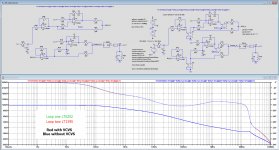
I could not give up looking for possible reasons in the discrepancies between the LT1395 and the LT6202.
So I went to the the open loop gain with a large inductance in series and a large Cap to gnd in the feedback line.
Here it is what I saw what really happened:
The LT1395 has a negative output impedance and the LT6202 has a positive output impedance
There are two inner loops with 2 op-amps per loop, connected with each others output through 2 resistors.
With opposite output impedances, mega voltages and currents became visible in the AC analysis mode when the two different types of op-amps where used in one loop.
However when using two of the same op-amps per loop, no matter if this was a LT1395 or a LT6202, everything was o.k.
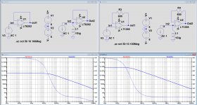
That's why I made the same circuit but now with behind each op-amp a VCVS to eliminate the influence of (opposite) output impedances.
This became the reference to compare to the versions without VCVS.
I have no idea whether the two different output impedances are correct for the real models models, but in an AC analysis it is ruining your model.
The first image below shows the "ideal" VCVS version with LT6202 amps to the right, and the one without VCVS to the left.
As can be seen, they are practically identical, where the VCVS version has a slightly higher loop gain at LF because the op-amps are seeing no load at all.
The second image shows again an "ideal" VCVS version with two LT1395 amps in the second loop at the right and at the left one without the VCVS.
Again completely the same. The LF gain is now much lower because of the LT1395's lower open loop gain.
So careful conclusion may be that seemingly neither LTspice nor the models can be blamed for the odd AC Analysis results with Tian.
Hans
Attachments

Thanks for your input, very informative.
When I started simulating with LTSpice more than 10 years ago, nearly every simulation
that I tried failed, often to even get the bias points correct - mostly due to "stupid parameters values"
as you put it. When I moved to Cordell's models I was able to get reasonable results.
They may be "crap" models but at least they are not broken models.
Do you have a suggestion for a source for free models or even a better free simulator with models?
I am curious about this too. Compared to the IC industry the Cordell models are pretty primitive, but as Peter says, they work (i.e. they are not broken).
If anyone can point to free MEXTRAM models, that would be awesome. I am afraid they do not exist though.
FYI, at Analog Devices we used Mextram exclusively for all our internal processes (at least as of 4 years ago).
Wonders still happen,Damir,
I mentioned that with main amps LTSpice can give results that are hard to understand.
For that I mentioned a Mark Levinson 23.5 Main amp.
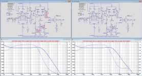
While repairing this amp, I could not get a stable model in LTspice, although having the official Madrigal document, see pdf below.
In the first image below, you see at the left the circuit diagram from the official documentation with four compensation caps encircled in red.
Below the circuit diagram you see the loop gain belonging to it, clearly indicating an unstable situation.
So I checked the PCB and all component values and they fully seemed to confirm the official circuit diagram.
Because I had to repair the amp, I first took out those 4 caps and replaced them by a 100pF Cdom around the VAS, see right part of the image.
The loop gain in LTspice confirms a stable situation now.
After having repaired the amplifier still with the 100pF Cdom, I compared it to the other channel that was still intact and in original state.
And of course this channel was absolutely stable as expected but only with those 4 caps as in the original documentation.
Behaviour between the two channels was quite comparable in THD and for square wave response, a complete mystery.
There are several possibilities:
1) LTSpice is confused by this compensation and gives a wrong outcome
2) There is some undocumented component mounted, but despite all effort I can't find it.
The above is what I wrote in october, telling that LTSpice predicted an unstable situation, where the real Mark Levinson 23.5 amp was stable.
Since I'm planning to redesign the PCB, I went back to the sim that was unaffected after I reported the above.
The only thing that changed in the meantime where a few LTSpice updates.
So much to my surprise I got a different response, now resulting in a stable amp, although still with a relatively small phase margin, but nevertheless.
Also the voltages are slightly different, isn't this a nice surprise ?
Hans
Attachments
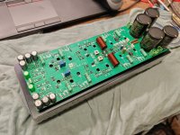
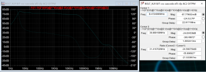
Happy to report that OITPC works 100%. So far done some basic checks, stability is OK, THD is lower than my focusrite 2i2 so there is no point of placing any measurements. Amp is fast and sounds great. Have some test's left to do with reactive loads. Only thing I was not sure about is the ''deep'' in phase (Bode plot) going to near 160deg (a bit too close to 180deg), but amp is stable anyway.
BIG THANKS to Damir !!!
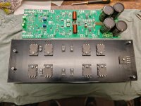
Had opportunity to measure DF (pcb has two separate channels for XLR, so used 2nd one as a ''GND'').
DF measured at the output inductor is about 3500 - 4000 (40Vp-p @8R 1kHz) . After the inductor I placed SPK protect circuit with mosfet relay (2x RdsON added), so at the amp output I am getting DF about=450.
Question, does anyone experimented with NFB to be directly from the output terminal ?
Regards
BIG THANKS to Damir !!!
Had opportunity to measure DF (pcb has two separate channels for XLR, so used 2nd one as a ''GND'').
DF measured at the output inductor is about 3500 - 4000 (40Vp-p @8R 1kHz) . After the inductor I placed SPK protect circuit with mosfet relay (2x RdsON added), so at the amp output I am getting DF about=450.
Question, does anyone experimented with NFB to be directly from the output terminal ?
Regards
Attachments
Don't worry abouth that phase deep, it is normal for two pole compensation.
What amp is this, could you show schematic?
What amp is this, could you show schematic?
It might still cause problems in some edge cases.Don't worry abouth that phase deep, it is normal for two pole compensation.
At the phase dipping region, as long as the loop gain stay above zero, it would be fine. However, when the amp is slew rate limited or during the clipping, the actual gain drops comparing to the small signal simulation. In this situation, it might cause issue.
Bellow is the schematic. Really simple, nothing spectacular.Don't worry abouth that phase deep, it is normal for two pole compensation.
What amp is this, could you show schematic?

I have simulated a good few of differed loads and that phase deep is about in same place.
Bellow 8R@2,8VRMS--> 1kHz

Bellow 8R@2,8VRMS --> two sine

Bellow 8R@5,6VRMS --> 1kHz + two sine


Measurements are not 100% as I am limited to focusrite 2i2 gen3 which ADC is not the top performance + no enclosure for it yet.
My question is still open: ''how about taking NFB right from speaker terminal ?''.
Just wondering if it makes any sense? There is a bit of the work to switch NFB point during startup (while protection circuit is switching OFF/ON), is it worth it ?
Thanks
Last edited:

- Home
- Amplifiers
- Solid State
- OITPC - Output inclusive TPC (not TMC)