I wanted to see your composite amplifier in a microcapI don't understand your question, but when you ask for the LT1395 Netlist, I must disappoint you because that's hidden deep inside LTspice.
Hans
I tried a number of things around the LT1395 buffer.
Placing a VDVS in front of In+ to eliminate the source impedance made no difference to the earlier shown weird phase results.
But using a VDVS behind the LT1395's output resulted all at the sudden in a correct open loop phase behaviour.
Adding additional load from 10R up to 10Gig to the output of the LT1395 made no difference at all.
See both versions without and with load in the image below including the VDVS, both now with correct phase behaviour.
Source impedance of the buffer's input seems to play no role and loading it's output neither.
Here is some magic at work that I can't explain.
Either there is something very weird with the LT1395 model, or LTspice get's confused by whatever reason.
Hans
Can you please simulate a stand alone LT1395 buffer non inverting input and output impedances vs. frequency? Use the definition, in an AC analysis inject a current and read the voltage across. Sorry, I am not a LTSpice user.
Too bad very few people use Micro Cap 12, now it also free, also powerful but much simpler, LTspice is a nightmare to me...
Not to mention that TI is now offering the latest Cadence PSpice version for free.
Can you please simulate a stand alone LT1395 buffer non inverting input and output impedances vs. frequency? Use the definition, in an AC analysis inject a current and read the voltage across. Sorry, I am not a LTSpice user.
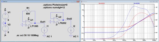
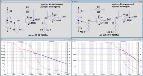
Here they are, the output impedances for the LT1395 and for the LT6202 that where both used in my previous examples.
Hans
Attachments
Why do I need the l T 1395 output stage circuit? I model it by adding a simple symmetrical repeater on transistors of different structures and setting the quiescent current of this stage equal to the quiescent current of the operational amplifier .I don't understand your question, but when you ask for the LT1395 Netlist, I must disappoint you because that's hidden deep inside LTspice.
Hans
I can show you the diagram
In the microcap, the LT1395 model is incomplete.
Last edited:
Here they are, the output impedances for the LT1395 and for the LT6202 that where both used in my previous examples.
Looks good. And the non inverting input impedance of the LT1395?
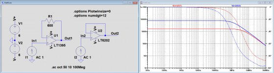
Here are the input impedances of both op-amps.
Hans
Hi Hans,
Have you tried different value for R1(lower)?
Damir
Hi Damir,
Yes, I have tried different values for R1 with no effect on the strange phase behaviour.
For a 0dB gain buffer setting, the 600R gives the flattest FR as shown in posting #193.
This is an example somewhat similar as the Mark Levinson 23.5 amp: the real thing is working without any flaws, but LTspice takes a wrong exit somewhere.
Hans
P.S. I also tried LTspice IV, but response was identical to LTspice XVII
Last edited:
The input impedances look a little odd, 18k at LF is rather low even for a CFA. It is also rather odd that this actually works in the simulator, these are both bipolar devices and the input bias current has no path, it is quite large (10uA for the LT1395, 1.5uA for the LT6202) according to the data sheet, do these amplifiers bias correctly when determining the input impedance?
Assuming they somehow bias correctly, now a tougher one. In the original schematic, remove the Tian probe and try to reproduce the jumping loop gain phase using a less precise method (but which is good enough for 99% of cases). You probably know the trick, insert the AC voltage source in the feedback loop and calculate the magnitude and phase of the ratio between the output voltage (right end of the AC source) and the feedback loop input voltage (left end of the AC source). This method ignores the contribution of the current gains to the loop gain, which is again, acceptable in 99% of the amplifiers we deal with.
If the phase still looks incorrect without the VCVS (compare with the Tian probe result), then this is likely a device model issue (which I believe it is the case here). If the phase is now correct in both cases, then it is likely a LTSpice problem.
Damir,
I mentioned that with main amps LTSpice can give results that are hard to understand.
For that I mentioned a Mark Levinson 23.5 Main amp.
While repairing this amp, I could not get a stable model in LTspice, although having the official Madrigal document, see pdf below.
There are several possibilities:
1) LTSpice is confused by this compensation and gives a wrong outcome
2) There is some undocumented component mounted, but despite all effort I can't find it.
Hi Hans,
I spent some time with your .asc files
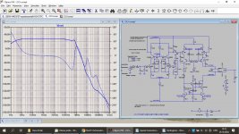
First I tried Loop Gain simulation using Tian probe and changing some transistors models for Corddel models in few steps and got similar result to yours, instability.
Then I simulated Close Loop Gain and tran, attached the plots.
There is something very strange with your sim schematic, I don't think it's LTspice problem.
CLG shows 26dB gain, but tran simulation with 0.2 Vp gives 76Vp at the output????
Damir
Attachments
Assuming they somehow bias correctly, now a tougher one. In the original schematic, remove the Tian probe and try to reproduce the jumping loop gain phase using a less precise method (but which is good enough for 99% of cases). You probably know the trick, insert the AC voltage source in the feedback loop and calculate the magnitude and phase of the ratio between the output voltage (right end of the AC source) and the feedback loop input voltage (left end of the AC source). This method ignores the contribution of the current gains to the loop gain, which is again, acceptable in 99% of the amplifiers we deal with.
If the phase still looks incorrect without the VCVS (compare with the Tian probe result), then this is likely a device model issue (which I believe it is the case here). If the phase is now correct in both cases, then it is likely a LTSpice problem.
Attached, the same as with Tian probe.
Attachments
The input impedances look a little odd, 18k at LF is rather low even for a CFA. It is also rather odd that this actually works in the simulator, these are both bipolar devices and the input bias current has no path, it is quite large (10uA for the LT1395, 1.5uA for the LT6202) according to the data sheet, do these amplifiers bias correctly when determining the input impedance?
I think I'm getting mad.
Bias current is resp 3uA and 10uA for both amps, that seems reasonable.
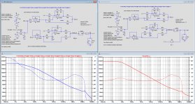
BUT, I measured the input impedance now two times, one with Voltage sources and the other with Current sources.
Outcome should be the exactly same when measuring the input voltage and dividing it by the input current, right ?
Well they are not by a large margin.
See image below.
Hans
Attachments
Hi Hans,
I spent some time with your .asc files
First I tried Loop Gain simulation using Tian probe and changing some transistors models for Corddel models in few steps and got similar result to yours, instability.
Then I simulated Close Loop Gain and tran, attached the plots.
There is something very strange with your sim schematic, I don't think it's LTspice problem.
CLG shows 26dB gain, but tran simulation with 0.2 Vp gives 76Vp at the output????
Damir
Hi Damir,
Thank you for taking the trouble to spend some time with the model.
Why do you think it's not an LTspice problem ?
It is to the slightest detail exactly the Mark Levinson 23.5, did you check the original PDF documentation ?
And when you put a 100pF cap to the upper Vas side and remove the lower 470pF, you have a perfectly working amp in LTspice, see again posting #183
OITPC - Output inclusive TPC (not TMC)
As mentioned in that posting I have tried this 100pF change on the real amp too, and it behaved almost exactly like the original version with the lower 470pF in THD, bandwidth and square wave response.
So for me it's an obvious direct or indirect LTspice problem for whatever reason.
Hans.
All clear, poor model(s).
Spice models usually specify what they are good for; some are for AC only (no DC or transient), some are transient only (like the LM3886 encrypted power amplifier model) some are DC only (some chopper op amps). There are very few device level spice model, that may have a chance to cover all 3 domains, one is notably the LM49710 and LM4562 (same but dual). Most of them are behavioral models, with ideal elements.
Don't take me wrong, behavioral models can be great; for example all microwave devices are modeled as tables of Sij parameters, with no direct relationship to the underlying device physics (like, for example, the Gummel-Poon model for bipolars). However, the models available for free are cheap first order approximations, with limited applicability. Buy 1M of LM1395 devices and make no mistake, AD will give you, at your request, precise model(s) that will simulate perfectly in the applications you may want to develop. Device modelling is a very expensive activity.
Perhaps it is now clear why I am so skeptical on Spice only designs and results, without any support in analytical and measurement results.
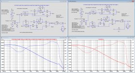
Here are the two different sims, to the left with Tian and to the right with a voltage source in the feedback loop.Originally Posted by syn08
Now a tougher one. In the original schematic, remove the Tian probe and try to reproduce the jumping loop gain phase using a less precise method (but which is good enough for 99% of cases). You probably know the trick, insert the AC voltage source in the feedback loop and calculate the magnitude and phase of the ratio between the output voltage (right end of the AC source) and the feedback loop input voltage (left end of the AC source). This method ignores the contribution of the current gains to the loop gain, which is again, acceptable in 99% of the amplifiers we deal with.
If the phase still looks incorrect without the VCVS (compare with the Tian probe result), then this is likely a device model issue (which I believe it is the case here). If the phase is now correct in both cases, then it is likely a LTSpice problem.
Shape of the phase is exactly the same between both methods, but 180 degrees shifted.
I have also applied both loop gain methods to the version with the LT6202, and also here a 180 degrees phase shift but now with a different phase shape.
Hans
Attachments
Hi Damir,
Thank you for taking the trouble to spend some time with the model.
Why do you think it's not an LTspice problem ?
It is to the slightest detail exactly the Mark Levinson 23.5, did you check the original PDF documentation ?
Hans.
Hi Hans,
I think it's models problem as syn08 says.
This Mark Levinson amp as some other Mark Levinson amps is so complicated using unusual transistors. I tied to change some for Cordell models or other models I'm confident in, but others I don't have good models.
Are you sure in quality in your models?
Damir
Perhaps it is now clear why I am so skeptical on Spice only designs and results, without any support in analytical and measurement results.
I can only agree for 100%.
The specific amp with the LT1395 was designed 6 years ago with pen and paper without LTspice and came to life on the bench.
When I simulated the thing at a later instant, I was surprised by the impossible results.
It's now obvious that it has everything to do with the quality of the component models.
The Mark Levinson amp, designed 40 years ago most likely without Spice, is just another example where reality and simulation don't meet by a large margin, most likely also because of the quality of the component models.
But whatever the cause is, you have to be very careful.
Fortunately, most of the time design and results do correspond in the most accurate way.
Thank you for your support.
Hans
Hi Hans,
I think it's models problem as syn08 says.
This Mark Levinson amp as some other Mark Levinson amps is so complicated using unusual transistors. I tied to change some for Cordell models or other models I'm confident in, but others I don't have good models.
Are you sure in quality in your models?
Damir
The transistors that are unusual are the MPSA14 and the MPSA64 darlingtons, and to be honest, I have no idea how well the Motorola models are.
The other transistors models may be reasonable correct, but may be not.
So let's agree that the transistor models are to blame, but in this case I'm rather surprised because the amp is basically not that complicated: IPS is a straightforward LTP, a balanced VAS and a three stage EF OPS.
But the whole exercise was just as Syn08 mentioned to show that you can't always rely on what LTspice produces.
Hans
Here are the two different sims, to the left with Tian and to the right with a voltage source in the feedback loop.
Shape of the phase is exactly the same between both methods, but 180 degrees shifted.
I have also applied both loop gain methods to the version with the LT6202, and also here a 180 degrees phase shift but now with a different phase shape.
An 180 degrees phase shift is fine, after all the phase origin is not well defined, you always eventually have to normalize it.
The LT6202 results are definitely wrong, what LTSpice says is a physical impossibility.
Bottom line, crap models. You got what you payed for 😀.
P.S. I fail to understand the unconditional trust in the Cordell models; as far as I can tell, they are pretty much stock models, without any extra advanced features, only corrected here and there for the obvious stupid parameters values, like Beta=8215, or VAF=2314V as sometimes included in the Mextram parameter extraction BS. In probably 99.9% of cases, if you get crap results with the original models, you will get the same with the Cordell models. At least when it comes to transient simulation, since little to nothing of the second order effects are modeled (quasi-saturation, etc...) not much (if any) results (like THD, clipping behavior, etc...) accuracy improvements should be expected by using the Cordell models.
Last edited:
- Home
- Amplifiers
- Solid State
- OITPC - Output inclusive TPC (not TMC)