The purpose of having a discussion is to learn something from each other.
But often people feel atacked and start defending themselves, keeping their cards close to their chests and stop responding to questions.
That’s a real pitty because some really interesting things were brought forward that could have led to new insights.
I can only agree that LTSpice is a fantastic tool to prepare things, but with main amps you can be mislead by a great margin. And comparing different compensation forms do not tell anything about the quality of the sound reproduction at all as long as we don’t know what to look at.
I have repaired a Mark Levinson 23.5 for someone, of which I tried to simulate which broken component could cause the same misbehaviour.
No chance at all.
Even after repair, this amp having some very strange two pole compensation network around the VAS, it was impossible to get the same square wave response with LTSpice. In this case the amp behaved much better but it could just as well have been the other way round.
So LTSpice results have always to be regarded with great care when used to prove something.
Just my 2 cents.
Hans
The purpose of having a discussion is to learn something from each other.
So LTSpice results have always to be regarded with great care when used to prove something.
Just my 2 cents.
Hans
Hans, I agree with you, for me syn08 participation is very important(In my opinion his knowledge is probable one of highest here in this forum much higher then mine, some don't like his communication way but I don't care if I learn something from).
Regarding LTspice, it is not only fantastic and free, but will give result very close to real thing, deepens of used models and skell of the user.
Damir
Damir,
I mentioned that with main amps LTSpice can give results that are hard to understand.
For that I mentioned a Mark Levinson 23.5 Main amp.
While repairing this amp, I could not get a stable model in LTspice, although having the official Madrigal document, see pdf below.
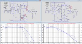
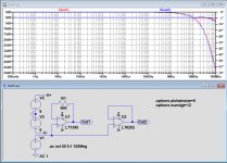
In the first image below, you see at the left the circuit diagram from the official documentation with four compensation caps encircled in red.
Below the circuit diagram you see the loop gain belonging to it, clearly indicating an unstable situation.
So I checked the PCB and all component values and they fully seemed to confirm the official circuit diagram.
Because I had to repair the amp, I first took out those 4 caps and replaced them by a 100pF Cdom around the VAS, see right part of the image.
The loop gain in LTspice confirms a stable situation now.
After having repaired the amplifier still with the 100pF Cdom, I compared it to the other channel that was still intact and in original state.
And of course this channel was absolutely stable as expected but only with those 4 caps as in the original documentation.
Behaviour between the two channels was quite comparable in THD and for square wave response, a complete mystery.
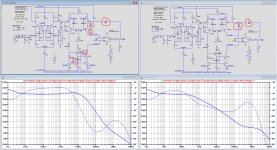
Then I tried to get a stable amp in LTspice starting with the original diagram.
This was possible by adding a 300pF cap from output to VAS input, the loop gain now showing >40 degrees phase margin.
When somewhere this cap would have been physically there but not in the documentation, It would still be there in my simple version with the 100pF Cdom.
But adding this 300pF cap to my simple Cdom version, results in an unstable amplifier but also the 0dB loop gain is now at ca 5Mhz instead of the measured 350Khz.
So this cap is definitely not there.
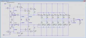
For completeness I have added the three stage emitter follower output, which is simple and straightforward.
Last but not least, I can mention that the smaller ML27.5 brother is almost a copy , but with only four TO3 pairs instead of six and with a lower supply voltage, see fourth image.
The compensation is even simpler without the 22pF and the 47pF of the ML23.5.
There are several possibilities:
1) LTSpice is confused by this compensation and gives a wrong outcome
2) There is some undocumented component mounted, but despite all effort I can't find it.
I mentioned that with main amps LTSpice can give results that are hard to understand.
For that I mentioned a Mark Levinson 23.5 Main amp.
While repairing this amp, I could not get a stable model in LTspice, although having the official Madrigal document, see pdf below.
In the first image below, you see at the left the circuit diagram from the official documentation with four compensation caps encircled in red.
Below the circuit diagram you see the loop gain belonging to it, clearly indicating an unstable situation.
So I checked the PCB and all component values and they fully seemed to confirm the official circuit diagram.
Because I had to repair the amp, I first took out those 4 caps and replaced them by a 100pF Cdom around the VAS, see right part of the image.
The loop gain in LTspice confirms a stable situation now.
After having repaired the amplifier still with the 100pF Cdom, I compared it to the other channel that was still intact and in original state.
And of course this channel was absolutely stable as expected but only with those 4 caps as in the original documentation.
Behaviour between the two channels was quite comparable in THD and for square wave response, a complete mystery.
Then I tried to get a stable amp in LTspice starting with the original diagram.
This was possible by adding a 300pF cap from output to VAS input, the loop gain now showing >40 degrees phase margin.
When somewhere this cap would have been physically there but not in the documentation, It would still be there in my simple version with the 100pF Cdom.
But adding this 300pF cap to my simple Cdom version, results in an unstable amplifier but also the 0dB loop gain is now at ca 5Mhz instead of the measured 350Khz.
So this cap is definitely not there.
For completeness I have added the three stage emitter follower output, which is simple and straightforward.
Last but not least, I can mention that the smaller ML27.5 brother is almost a copy , but with only four TO3 pairs instead of six and with a lower supply voltage, see fourth image.
The compensation is even simpler without the 22pF and the 47pF of the ML23.5.
There are several possibilities:
1) LTSpice is confused by this compensation and gives a wrong outcome
2) There is some undocumented component mounted, but despite all effort I can't find it.
Attachments

Last edited:
Hans,
I don't think LTscice is confused, always when LTspice showed something strange it was my fault.
For completeness I have added the three stage emitter follower output, which is simple and straightforward. ?
If you didn't do it already, try to simulate whole amp with ops connected. Could be that unloaded input/TIS stage will show instability.
This amp is so complicated, and some people say I do complicated amps.🙂
Damir, thank you for answerring.
The OPS was of course connected, but as a subcircuit.
It was the little rectangle before the loop gain probe, that’s why I showed it separetely in the third image.
So this simulation represents the whole amp including 8R load.
Point is as explained, that with a single pole compensation everyting works as expected.
Even TPC can be succesfully applied without a problem.
But not at all the strange compensation that ML applied.
I still can’t find any error in what I did.
Hans
I cannot come to any other conclusion than that LTspice is most likely going wrong somewhere.Hans,
I don't think LTscice is confused, always when LTspice showed something strange it was my fault.
All components and functions are thoroughly checked for many many times.
It is the first time I come across such a strange situation, but the prove is a functioning amplifier where LTspice is unable to simulate it, not even close.
If someone wants to play with it, let me know and I will make all the relevant files available.
Hans
OK Hans, I could try but no guaranty. It could take me some time, I am in middle of other amp construction.
Damir
Damir
I would try replacing all bipolar models with those from Cordell.
The dual model from AD is probably fine to leave.
The dual model from AD is probably fine to leave.
Last edited:
The input devices in the sim seem to have too much capacitance for this kind of design. I haven't run it. Just an idea.
Mark Levinson used both the LM394 and the Mat02 duals for the input LTP, they are excellent transistors for this purpose.
Hans
Hans
Many of us nowadays are used to start a design with LTspice before building, and we are seldom disappointed by the results that may come quite close.
This of course depending on the quality of the sim component models, the built quality of the real thing and the experience and know how of the guy doing it.
But in this Mark Levinson case, it's the other way round. We have a perfectly working Amplifier, but the sim model doesn't seem to be able to replicate this.
If true, it would implicate that LTspice still has uncovered areas that are limiting the design phase.
And as a matter of fact I still have other examples where the simulation is behaving odd.
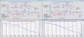
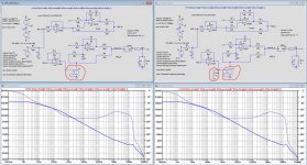
Look at the first image below.
Two 100% identical circuit diagrams with one difference:
Left one is using a fast LT1395 CFA buffer and the right one fast LT6202 VFA buffer.
Looking at the loop gain, one would think that the left one is highly unstable and the right one not.
Phase versus frequency is completely different between both.
Now putting a square wave to the input, gives exactly the same response at the output, because as expected both are 100% functionally equal but LTspice reacts completely different in the first image.
The third image confirms that LTspice gives almost identical responses for the LT1395 and the LT6202 op-amps including their phase behaviour.
Just another mystery, true ??
Hans
This of course depending on the quality of the sim component models, the built quality of the real thing and the experience and know how of the guy doing it.
But in this Mark Levinson case, it's the other way round. We have a perfectly working Amplifier, but the sim model doesn't seem to be able to replicate this.
If true, it would implicate that LTspice still has uncovered areas that are limiting the design phase.
And as a matter of fact I still have other examples where the simulation is behaving odd.
Look at the first image below.
Two 100% identical circuit diagrams with one difference:
Left one is using a fast LT1395 CFA buffer and the right one fast LT6202 VFA buffer.
Looking at the loop gain, one would think that the left one is highly unstable and the right one not.
Phase versus frequency is completely different between both.
Now putting a square wave to the input, gives exactly the same response at the output, because as expected both are 100% functionally equal but LTspice reacts completely different in the first image.
The third image confirms that LTspice gives almost identical responses for the LT1395 and the LT6202 op-amps including their phase behaviour.
Just another mystery, true ??
Hans
Attachments

This really should be a new thread.
We have noted for more than 10 years that MOST models you find are bad or
nearly defective. You need good models and otherwise are wasting your time.
We have noted for more than 10 years that MOST models you find are bad or
nearly defective. You need good models and otherwise are wasting your time.
Last edited:
I fail to see in the above example how a bad model could be o.k. as a buffer in one stuation as in the third image and can cause such a huge phase error in the first image.
Maybe you could come with some logical explanation.
Hans
Maybe you could come with some logical explanation.
Hans
A simulator problem cannot be excluded. What is really weird is that you got this problem during an AC analysis, which is essentially a linear problem. Linear systems have a guaranteed unique global solution, and while numerical rounding and Newton Raphson SOR convergence issues cannot be excluded, it is very unlikely they occur.
For DC and Transient analysis, this issue is a classic. The non linear problem to solve may have local convergence minima, and the solver may stubbornly stick to these, instead of looking for the global solution. At Cadence we even had some test cases for this behaviour, the software solution was to add some numerical noise around each local convergence point and see if the solution is stable, kind of noise modulation in the numerical domain.
No idea how ltspice works and if such issues are possible, I would try to change component values by small amounts and see if the solution jumps around. I would also take a look into the op amps models, some behavioural models are inviting such issues, since they use synthetic ideal elements, some time with little care for details like very high impedances in series or very low impedances in parallel.
I tried a number of things around the LT1395 buffer.
Placing a VDVS in front of In+ to eliminate the source impedance made no difference to the earlier shown weird phase results.
But using a VDVS behind the LT1395's output resulted all at the sudden in a correct open loop phase behaviour.
Adding additional load from 10R up to 10Gig to the output of the LT1395 made no difference at all.
See both versions without and with load in the image below including the VDVS, both now with correct phase behaviour.
Source impedance of the buffer's input seems to play no role and loading it's output neither.
Here is some magic at work that I can't explain.
Either there is something very weird with the LT1395 model, or LTspice get's confused by whatever reason.
Hans
Attachments
Please show the diagram of this node on the operational amplifiers .But not in ltspice. I want to watch it in MC-12
Last edited:
I don't understand your question, but when you ask for the LT1395 Netlist, I must disappoint you because that's hidden deep inside LTspice.
Hans
Hans
Too bad very few people use Micro Cap 12, now it also free, also powerful but much simpler, LTspice is a nightmare to me...
- Home
- Amplifiers
- Solid State
- OITPC - Output inclusive TPC (not TMC)