@ Bas :
... could not find a hint which manufacturer
you are using for your PCB's. Can you supply this info please
Looks like Prasi might have a pair BHEL84 PCBs left.
See:
https://www.diyaudio.com/forums/group-buys/312869-gb-baby-huey-pcb-136.html#post6459376
PCB earthing with external regulated supply
Thanks for this thread Bas. I've just started assembling my 2 EL84 PCBs. Your thread is a great resource.
I intend to use an external regulated supply as you have done.
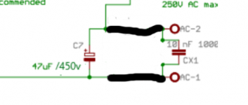
Just looking at the images you have posted it looks like you have connected the earth to AC-1 where the rectifying diodes D2 and D3 would have been joined.
This means that the whole board is earthed through the 3 little tracks around where the anode of D3 would have been as shown below.
Is that sufficient for up to 80mA?
Thanks for this thread Bas. I've just started assembling my 2 EL84 PCBs. Your thread is a great resource.
I intend to use an external regulated supply as you have done.
Just looking at the images you have posted it looks like you have connected the earth to AC-1 where the rectifying diodes D2 and D3 would have been joined.
This means that the whole board is earthed through the 3 little tracks around where the anode of D3 would have been as shown below.
Is that sufficient for up to 80mA?
Attachments

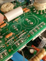
Does anyone have a pic of fully build power supply? I am about to complete my soldering, but don't know what kind of connectors does it use.
Here is a pic of my bare board

Regards
Sachin
Here is a pic of my bare board
Regards
Sachin
Thank you. This is useful.
One last question. What is the NTC value for EL84 build.
Regards
Sachin
One last question. What is the NTC value for EL84 build.
Regards
Sachin
I found the B.O.M.
the original specified connectors are
Phoenix FFKDSA1/V1-5.08-2
Phoenix FFKDSA1/V1-5.08-4
For the NTC - I just used what I had on hand which I believe was a CL-60
see this thread for discussion - they recommend CL-140
the original specified connectors are
Phoenix FFKDSA1/V1-5.08-2
Phoenix FFKDSA1/V1-5.08-4
For the NTC - I just used what I had on hand which I believe was a CL-60
see this thread for discussion - they recommend CL-140
Last edited:
There are a few things to be aware of with the PSU.
1) The capacitor C9 (I believe) needs to be altered to get the right delay for power on.
2) Some of the resistors need to be tweaked to get the fixed bias supply in the right range for adjustment on the amplifier board.
3) Two of the pins of the FET have to be switched.
If you were to start a thread on the BH PSU, I'll check the information I have, and others can chip in, and then there would be a one stop shop for building the PSU.
Hello, these transformers that you suggest Gegentaktubertrager ATR 30 fur EL 84 | TBT Trafobau, someone has tried them. They have a great price, they are worth it.
There are a few things to be aware of with the PSU.
1) The capacitor C9 (I believe) needs to be altered to get the right delay for power on.
2) Some of the resistors need to be tweaked to get the fixed bias supply in the right range for adjustment on the amplifier board.
3) Two of the pins of the FET have to be switched.
If you were to start a thread on the BH PSU, I'll check the information I have, and others can chip in, and then there would be a one stop shop for building the PSU.
Sorry
I just read the replies. I didn't get any notification. Could you please tell me the modified values of caps and resistors. I can definitely start a new thread but I think I won't get many replies.
Regards
Sachin
Hmm! That is the problem with these boards.
Could we urge some disciple! First posters to keep the first post updated with the current schematics, BOMs etc!
Could we urge some disciple! First posters to keep the first post updated with the current schematics, BOMs etc!
Sorry
I just read the replies. I didn't get any notification. Could you please tell me the modified values of caps and resistors. I can definitely start a new thread but I think I won't get many replies.
Regards
Sachin
You will get no notifactions, sadly. You have to read the thread from the beginning to get the info you needed.
Hmm! That is the problem with these boards.
Could we urge some disciple! First posters to keep the first post updated with the current schematics, BOMs etc!
My apologies, Bas. This sounds like I was directing my comment at you, which was not my intent at all.
It was a general comment for all of us who start threads to exercise more discipline and use our first post editing privileges for good housekeeping.
I have tried the above connectors, but they aren't going in. Did you drill the PCb holes little wider?
Regards
Sachin
Last edited:
No, the fitted perfectly. I wonder if you bought ones with a wider pitch. Mine were 5mm, you might have 6.3mm.
Thanks,
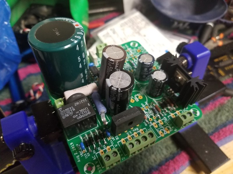
I got the correct ones now. Power supply board is almost ready. I ust wanted to confirm the value of C6. The BOM says 220uf , 25V and on PCB 2200uf, which one is correct? Also there is 100 nf printed on PCB for C16, BOM 10NF.
Someone suggested here that one transistor leg needs to be reversed? Can anyone confirm orientation of Q2 (2N3906) and Q1 (IRF9610)
I have also not soldered the LEDs and their orientation is confusing.
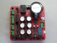
Here are some pics of Power supply and EL84 PCbs


Regards
Sachin
I got the correct ones now. Power supply board is almost ready. I ust wanted to confirm the value of C6. The BOM says 220uf , 25V and on PCB 2200uf, which one is correct? Also there is 100 nf printed on PCB for C16, BOM 10NF.
Someone suggested here that one transistor leg needs to be reversed? Can anyone confirm orientation of Q2 (2N3906) and Q1 (IRF9610)
I have also not soldered the LEDs and their orientation is confusing.
Here are some pics of Power supply and EL84 PCbs
Regards
Sachin
- Home
- Amplifiers
- Tubes / Valves
- Oh no...not another Baby Huey EL84 build.