Sachu888,
The correctted BOM is listed in this post
https://www.diyaudio.com/forums/tubes-valves/326920-el34-baby-huey-amplifier-64.html#post6045376
Be aware that this BOM was listed for an EL34/KT88 build, whereas you are using the PS PCB with a EL84 build, I think.
Also check #653 and 655 in the EL34 BH thread. EL34 Baby Huey Amplifier probiveds very useful voltage check points. Thank you Gabo!
Finally, the fix for the transistor leads are in https://www.diyaudio.com/forums/tubes-valves/326920-el34-baby-huey-amplifier-74.html#post6148566.
Good luck.
Last edited:
One more thing is that these bias points are for the EL34. I did not use the psu bias circuit for the EL84 build but rather the bias circuit already on the EL84 board. This means that you don't need the mosfet for this circuit.
The capacitor you were asking about is for the heater supply, use whatever 25v capacitor you have that fits. The value really doesn't matter. Remember that this build requires a DC-DC buck regulator for the heater supply to get you to the required 6.3V.
..dB
The capacitor you were asking about is for the heater supply, use whatever 25v capacitor you have that fits. The value really doesn't matter. Remember that this build requires a DC-DC buck regulator for the heater supply to get you to the required 6.3V.
..dB
Thanks FrancoisSachu888,
The correctted BOM is listed in this post
https://www.diyaudio.com/forums/tubes-valves/326920-el34-baby-huey-amplifier-64.html#post6045376
Be aware that this BOM was listed for an EL34/KT88 build, whereas you are using the PS PCB with a EL84 build, I think.
Also check #653 and 655 in the EL34 BH thread. EL34 Baby Huey Amplifier probiveds very useful voltage check points. Thank you Gabo!
Finally, the fix for the transistor leads are in https://www.diyaudio.com/forums/tubes-valves/326920-el34-baby-huey-amplifier-74.html#post6148566.
Good luck.
I have got the correct values according to that post. I am building EL 84 version, so I think I don't need to fix the transistor lead.
Regards
Sachin
Thanks!!One more thing is that these bias points are for the EL34. I did not use the psu bias circuit for the EL84 build but rather the bias circuit already on the EL84 board. This means that you don't need the mosfet for this circuit.
The capacitor you were asking about is for the heater supply, use whatever 25v capacitor you have that fits. The value really doesn't matter. Remember that this build requires a DC-DC buck regulator for the heater supply to get you to the required 6.3V.
..dB
I am only soldering PCBs for my friend. The final wiring will be done by him. I just want to make sure I solder proper value components before sending it to another country.
I will post the pics after I complete my soldering.
Regards
Sachin
One more thing is that these bias points are for the EL34. I did not use the psu bias circuit for the EL84 build but rather the bias circuit already on the EL84 board. ...
Good point dBel84! I should have made it clearer in my post. Thanks for making that clear, not to confuse the settings for the BH EL84 with the EL34/KT88 build.
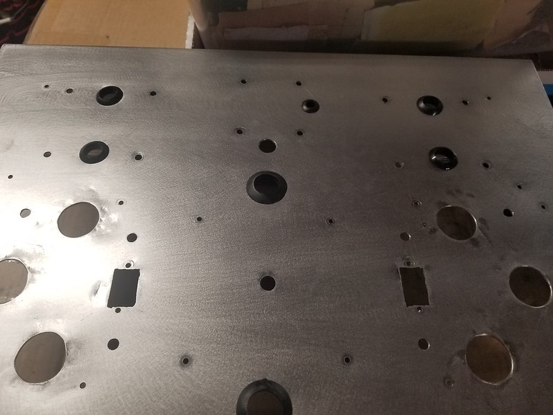
I finally found a little time to do the metal work and assembled the amp - still needs sides and feet but at least it is not a spaghetti junction of wires on my desk.
Here are a few pictures:
Stainless steel sheet with holes cut out and fitted rubber grommets to protct the wires
Started to assemble - IEC for power, binding posts and transformers fitted

Fitting the boards
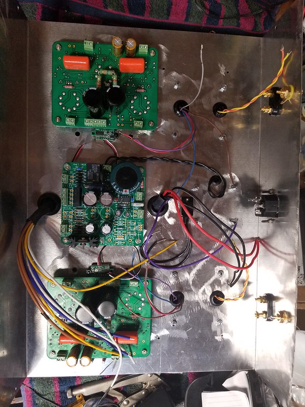
And after a much longer time than I thought it would take, finally wired up

It still needs the sides but all assembled and working - sounding very promising indeed

The little switches are for the bias - one powers up the led display and the other selects the tube - works very well and the little voltmeters are adjustable, so I set them to read the same as my multimeter and now I have confidence that it can be set very easily.
thanks to all who helped guide me through this project ( and of course the designer who shared the idea )
..dB
Here are a few pictures:
Stainless steel sheet with holes cut out and fitted rubber grommets to protct the wires
Started to assemble - IEC for power, binding posts and transformers fitted
Fitting the boards
And after a much longer time than I thought it would take, finally wired up
It still needs the sides but all assembled and working - sounding very promising indeed
The little switches are for the bias - one powers up the led display and the other selects the tube - works very well and the little voltmeters are adjustable, so I set them to read the same as my multimeter and now I have confidence that it can be set very easily.
thanks to all who helped guide me through this project ( and of course the designer who shared the idea )
..dB
Thank you . I have been listening all evening as I finish reading a few reports for work - really liking what I hear on my near field monitors - sadly a low level hum which I did not hear on my test speakers on my test bench but nothing audible when music is playing and probably wouldn't be heard normally except my speakers sit 3 feet from me.
Mids are very natural and top end is airy with lots of definition. Sound is crisp and snappy. Bass is present and deep but not as tight as with my first watt amps but still very good and pleasant to listen to ( ie not bloomy or bloated just a little rounded at the edge )
I am going to wear the little switches out as I cannot help myself "just checking" the bias 🙂
..dB
Congrats on getting the BH up and running. Getting that last bit of hum to disappear is sometimes a challenge. Looking at your under the deck layout it looks like the filament transformer is close to the left channel board and the leads for the primary of the OT. Particularly if the hum is higher in the left than right channels you could experiment with moving that transformer further from the board as well as perhaps just dressing the primary transformer leads further away to see if you can get any change in hum levels.
In the end you may need to switch to dc filaments to get rid of the last bit of hum.
I have a similar issue with my EL84 BH using AC on the filaments but I just haven’t had time to get back at it and figure out what is actually causing the hum. It really isn’t noticeable from the listening chair but if I was near field it probably would be.
I found the EL84 version to sound very nice, particularly on Jazz recordings, better in fact than the KT88 version I built, so that one will also be going back into development soon to see if I can up it’s game.
As luck would have it, the amp went miraculously quiet when I switched off the preamp after working last night = it is a tubed unity gain pre ( so more of a buffer ) but have never really heard any noise from it - I suspect the massive gain in the 12AX7s is amplifying what little noise there is and making it more obvious. The amp itself turns out to be silent.
The filament heaters on this amp are DC - I use the EL34 psu which puts out 15VDC for a buck regulator to step it down to 6.3V ( as in the BH EL34 )
I was a little worried about some of the rats nest wiring as I normally try not to cross wires too often . That was why I just assumed it was the amp with more sensitive speakers but luckily all it will need is a preamp switch out. I think I will add in a feedback switch to see how that impacts the sound too.
Can anyone tell me the orientation of LEDs on power supply board? I have completed soldering for all the boards except some small components.
Regards
Sachin
Regards
Sachin
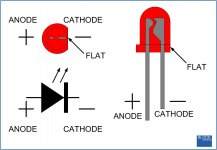
Is the problem identification/polarity of the LED leads? The board mask shows the LED as a circle with a “flat” side, so the flat side is the cathode.
If the physical LED has a flat area (on the plastic housing), the lead adjacent to the flat area is the negative (cathode) lead. Mount it flat side on the board to flat side on the physical LED
If no flat area and your LED has two leads, one longer than the other, the longer lead is the postive (also known as the anode) lead, short one is cathode.
Be sure to check the data sheet of your specific LED.
Attachments
Hi Francois
I am aware about LED shape. The amp boards are clearly marked for LED polarity. It's the power supply board where there is no marking.
Regards
Sachin
I am aware about LED shape. The amp boards are clearly marked for LED polarity. It's the power supply board where there is no marking.
Regards
Sachin
Sachu888,
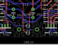
On this photo of the PSU board it shows the flat sides of the diodes (cathodes) on the right. Does your PCB not have the same mask?
On this photo of the PSU board it shows the flat sides of the diodes (cathodes) on the right. Does your PCB not have the same mask?
Attachments
Last edited:
Hi Francois
I think I have a different power supply boards. There are no polarity marked for LED. Here are couple of pics of my PCBs showing LEDs. Please click on the pics for correct orientation.


Regards
Sachin
I think I have a different power supply boards. There are no polarity marked for LED. Here are couple of pics of my PCBs showing LEDs. Please click on the pics for correct orientation.
Regards
Sachin
Dear Sachin,
take a look at the PSU schematic here: EL34 Baby Huey Amplifier
From that sachematic you can see that LED1's cathode is directly connected to Q2's collector (clearly shown in your first photo), and that LED2's cathode is directly connected ground (most probably the horizontal track that seems to go to the negative pin of the capacitor close to it).
Double check yourself.
I tested one of my boards and wanted to double-check a few values.
I ran through the bias procedure and set each EL84 to 38mA. (380mV across test points).
Also balanced the ECC83 to 0V.
B+ settles at 322V which seems fine.
For bias, I used a AN-0130 (2x 30V 0.15A):
*In series for 60VAC input, there is -69/77 VDC
*In parallel for 30VAC input, there is -33V/36 VDC
1) With 30VAC seems like bias supply is a touch too low. Is it ok with the 60VAC or is that too high?
2) Is 38mA a good target or is there a better value?
3) EL84 pin 9 (screen) to GND measures same as B+, around 320V. Shouldn't screen remain under 300V, or perhaps I am measuring the wrong thing here?
Thanks
Last edited:
322 V multiplied by 38 mA is 12,24 W, you are running too close to plate dissipation. I'd stay around 30-32 mA.
36Vdc is what I use.
Being UL shared on the same winding of the plates, screen and plates are at the same voltage with no voltage (a little bit higher, indeed).
36Vdc is what I use.
Being UL shared on the same winding of the plates, screen and plates are at the same voltage with no voltage (a little bit higher, indeed).
- Home
- Amplifiers
- Tubes / Valves
- Oh no...not another Baby Huey EL84 build.