Ok, so I have almost completed my EL84 boards. There is one question though. In the amp BOM CX1 is 10 nF or 100 nF, 1000V , but part no given for this 0.1uF 630volts X7R 10% cap https://www.mouser.in/ProductDetail...SvGap0Vm8lETFcU980mX8C4my/KMjB7UjjDSaVImWE3vx
but I have goth this Film Capacitors PP .01uF 630VDC 5% https://www.mouser.in/ProductDetail/KEMET/R79PC2100Z340J?qs=MdJgNetHbfk5SN3ucvZLng==
Is this ok to use?
Regards
Sachin
but I have goth this Film Capacitors PP .01uF 630VDC 5% https://www.mouser.in/ProductDetail/KEMET/R79PC2100Z340J?qs=MdJgNetHbfk5SN3ucvZLng==
Is this ok to use?
Regards
Sachin
Last edited:
36Vdc is what I use.
Is that about 50VAC to the bias input?
I guess I'm still confused about this. Where are you measuring 36VDC?
Given the half-wave rectification, my values shouldn't be that far off yours with the 60VAC transformers. I measured the +69/-66 across each of the 330uF caps.
Ok, so I have almost completed my EL84 boards. There is one question though. In the amp BOM CX1 is 10 nF or 100 nF, 1000V , but part no given for this 0.1uF 630volts X7R 10% cap https://www.mouser.in/ProductDetail...SvGap0Vm8lETFcU980mX8C4my/KMjB7UjjDSaVImWE3vx
but I have goth this Film Capacitors PP .01uF 630VDC 5% https://www.mouser.in/ProductDetail/KEMET/R79PC2100Z340J?qs=MdJgNetHbfk5SN3ucvZLng==
Is this ok to use?
Regards
Sachin
This is what I used: B32671P6104K000
Hi Francois
I am only soldering the boards for my friend.He will complete it in a. Chassis. I will ask him.
Regards
Sachin
I am only soldering the boards for my friend.He will complete it in a. Chassis. I will ask him.
Regards
Sachin
Sachu888,
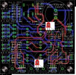
On this photo of the PSU board it shows the flat sides of the diodes (cathodes) on the right. Does your PCB not have the same mask?
Hi Francois
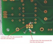
I run across a problems with power supply board. There is an IRF9610 P channel Mosfet. You can see the pic above. The 1N4742A diode's anode should connected to drain, cathode to source?
Where as on PCB : drain is connected to cathode and gate to anode? is this ok? or should I reverse the mosfet orientation or just reverse the diode?
Regards
Sachin
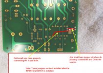
IRF9610 PCB correction, drain and source are swapped !
Attachments

Last edited:
there is also a mod --->
https://www.diyaudio.com/forums/tubes-valves/326920-el34-baby-huey-amplifier-72.html#post6145881
https://www.diyaudio.com/forums/tubes-valves/326920-el34-baby-huey-amplifier-74.html#post6148566
https://www.diyaudio.com/forums/tubes-valves/326920-el34-baby-huey-amplifier-77.html#post6155912
https://www.diyaudio.com/forums/tubes-valves/326920-el34-baby-huey-amplifier-72.html#post6145881
https://www.diyaudio.com/forums/tubes-valves/326920-el34-baby-huey-amplifier-74.html#post6148566
https://www.diyaudio.com/forums/tubes-valves/326920-el34-baby-huey-amplifier-77.html#post6155912
IRF9610 PCB correction, drain and source are swapped !
Thanks for detailed explanation. I will do this now.
Regards
Sachin

with a little skill you can mount the IRF9610 a little higher on the heat sink and cross the pins by bending it
Thanks!! If I do this then no need to cut any traces and placing jumpers?
Also could you tell me the LEDs polarity if you have the same PCB?
Regards
Sachin
yes, no need to cut traces and placing jumpers,
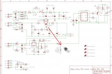
see corrected scheme !!!
see corrected scheme !!!
Attachments
Last edited:
can someone please explain to me what advantages it should have for the baby huey amplifier to use the external power supply board!?
Hi snapper,
Here is my understanding of the situation: The BH PSU PCB is required for the last version (Mk2) of the octal power amp (BHEL34 PCB), because it does not have rectifiers, etc, on board for bias or B+.
Marc (bandol83) really designed the PSU with the TOROIDY TSTA 0250/001 power transformer in mind, powering the “bigger-than-EL34” tubes like KT88, to provide a B+ delay relay start and better margins for bias and driver voltages. This also provides the DC current for the heaters via the buck converter that Marc suggested. (Other ways of heater arrangements are possible, naturally.)
The PSU board is not required for the earlier version of the BHEL34 PCB (if you do not plan to use the big power tubes), or the BHEL84 PCBs, which has the rectifiers on-board.
Here is Marc’s explanation for the PSU:
EL34 Baby Huey Amplifier
See the wiring diagram at the bottom of this post:
EL34 Baby Huey Amplifier
Of course you could use the PSU for the benefit of B+ delay, bigger smooting/storage caps etc.
P.S. Thanks snapper, for the helpful corrections of the wiring problem on the first edition of the PSU board. You are “Da Picture Man”! Future builder should note that a subsequent version of the PSU board had been corrected. Be sure to check!
Last edited:
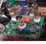
I have completed soldering of all three boards. They are now on the way to UK. I have twisted the legs of IRF9610 mosfet as suggested by Snapper. I didn't solder it on PCB as he may not need it for his EL84 build. Thanks everyone for their valuable support. If any one can correct power supply gerber files. I can get the good quality PCBs done and offer here if anyone interested.
Here are some pics


Regards
Sachin
Here are some pics
Regards
Sachin
hello Sachin
so far so good, but for a housing installation with visible EL84 it would have been better to put the 4 electrolytic capacitors and the terminal blocks on the other side of the board!
regards
so far so good, but for a housing installation with visible EL84 it would have been better to put the 4 electrolytic capacitors and the terminal blocks on the other side of the board!
regards
Attachments
Last edited:
- Home
- Amplifiers
- Tubes / Valves
- Oh no...not another Baby Huey EL84 build.