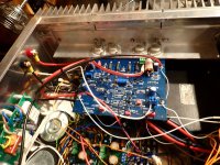
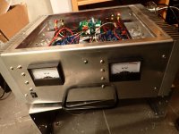
Hi everyone. Having built 3 Lang 20W class A amplifiers, after finishing the 4th, during the final measurements, the dc offset is 7mV at the right channel and at the left is -25mV. In all the previous amplifiers the offset voltage was between +5 to +13mV. The only difference among them is that instead of +-20V regulated voltage supply, +-28V unregulated power supply which I think it is not a big deal. My worst problem has been in matching the BC560C. i have bought 100 of them and their Hfe was below 600 except of 2. So While all the BC550C were from 600 to 612, I have placed the only 2 BC560C with Hfe 600 at the differential amplifier and the rest where it has been needed to. The quiescent current was set for 2A as per the instructions of the article. I use separate toroid transformers with 2 separate secondaries 2 X 20VAC/8A and 4 X 6 X10.000uF so every negative and positive voltage use 60.000uF each. All the components have been purchased by Mouser except the BC560C. The output waveform are clean and undistorted at 1Khz/4V input from the wave generator. Do you think that those difference will affect the fidelity of the amplifier and if yes how can I fix it? Check the attached files for every helpful detail. Thanks a lot in advance.
Attachments
That level of offset is really a non issue. If you work out the current in 8 ohms and the power it really is a quarter of a half of nothing 😉
As well as matching transistors have you also matched the Zener voltages for the current sources? That might swing things a little either way.
As well as matching transistors have you also matched the Zener voltages for the current sources? That might swing things a little either way.
I actually operate the amplifier with Cerwin Vega AT100/ 4ohm/97db. The reason I blame the BC560C is because, in a previous construction with the Elektor AXL, if you do not much the BC560C, the offset voltage climps up to 60mV. No I haven't check the zeners for 2 reasons. 1st I didn't know I had to and 2nd I thought that purchasing parts from Mouser, there is a standard quality. The previous 3 amplifiers had really no problem at all. I will check the quiescent current for any unbalancing issues between the channels.That level of offset is really a non issue. If you work out the current in 8 ohms and the power it really is a quarter of a half of nothing 😉
As well as matching transistors have you also matched the Zener voltages for the current sources? That might swing things a little either way.
I would imagine the Zener's must influence the offset because any change in the voltage across the Zener directly changes the current source value. Just measure the voltage across each. You could even try swapping them around and seeing if the offset alters closer to zero.
I will but swapping the zeners is a surgeon's job🙂. The zeners are so small that I can only cut their bodies carefully leaving their leads soldered and swap them resoldering as I can't really stand disassembling the heatsink and the circuit board from the enclosure of the amp.I would imagine the Zener's must influence the offset because any change in the voltage across the Zener directly changes the current source value. Just measure the voltage across each. You could even try swapping them around and seeing if the offset alters closer to zero.
Attachments
There is also a basic DC unbalance in the input stage. The input side base currents flow through more than 50k (47k + 4.7k), while on the feedback side it's 18k. That makes matching the transistors pretty much useless for DC offset.
Change the input side 47k to 12k and it'll probably all improve. And 12k is still a very nice input impedance.
Jan
Change the input side 47k to 12k and it'll probably all improve. And 12k is still a very nice input impedance.
Jan

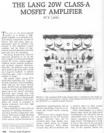
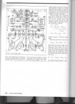
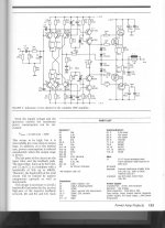
It's a classic class A amplifier for mid80's using the legendary Hitachi 2SJ48,49,50 and 2SK148,149,150 mosfets. In 1989 I built the elektor's AXL class A 2X16W with 1A quiescent current which is still working perfectly. I have decided to built that project because I have some Hitachi mosfets in stock and i wanted 4 more watts in class A.Very similar to Jean Marc (from France, Selectronics) amplifiers.
Jean Marc Plantefeve ?Très similaire aux amplificateurs Jean Marc (France, Selectronics).
I suppose the measurements must be taken across the zeners with no input and load.Measure the voltage across them as a first step and see if there is any difference
Yes, measure across the Zener. Operating conditions such as load or no load etc should make no difference at all.I suppose the measurements must be taken across the zeners with no input and load.
Well, after rechecking the amp quiescent current, i found it had been around 2,5A. I adjusted both right and left channel values at 2A. The offset voltage lowered from 8mV to 5,8mV at the right channel and from 25mV to 22,1mV at the left. Measuring the zeners with no load and input I got the following: RIGHT CHANNEL( Offset V 5,8mV)// 12V zener = -3,42V and -2,79V / 18V zener= -17,8V and -17,72V / 3,9V zener= -3,43V and -3,72V LEFT CHANNEL (Offset V 22,1mV) // 12V zener= -3V and -3,95 / 18V zener= -18 and -18 / 3,9V zener= -3,7V and -3,72V.Measure the voltage across them as a first step and see if there is any difference
The offset voltage is negative at both sides( -5,8mV and -22,1mV)Well, after rechecking the amp quiescent current, i found it had been around 2,5A. I adjusted both right and left channel values at 2A. The offset voltage lowered from 8mV to 5,8mV at the right channel and from 25mV to 22,1mV at the left. Measuring the zeners with no load and input I got the following: RIGHT CHANNEL( Offset V 5,8mV)// 12V zener = -3,42V and -2,79V / 18V zener= -17,8V and -17,72V / 3,9V zener= -3,43V and -3,72V LEFT CHANNEL (Offset V 22,1mV) // 12V zener= -3V and -3,95 / 18V zener= -18 and -18 / 3,9V zener= -3,7V and -3,72V.
Interesting results, thanks 🙂
The 12 volt Zener is for protection and should never come into play. They are fine.
The channel with the lowest offset seems to have the biggest variation with the 3.9 volt Zeners at 3.43 and 3.72 volt.
I'm going to say that what you are seeing offset wise is perfectly acceptable and that to get it lower is going to be a matter of luck as much as anything else. It really is a case of swapping parts (input transistors) I'm afraid to try and get a better 'fit' but what you have now is not a problem.
Remember that offsets of -/+ 100mv were considered acceptable some years back. Even that level does not cause any issues.
Thank you very much . I will keep it as is. Besides It sounds great .Interesting results, thanks 🙂
The 12 volt Zener is for protection and should never come into play. They are fine.
The channel with the lowest offset seems to have the biggest variation with the 3.9 volt Zeners at 3.43 and 3.72 volt.
I'm going to say that what you are seeing offset wise is perfectly acceptable and that to get it lower is going to be a matter of luck as much as anything else. It really is a case of swapping parts (input transistors) I'm afraid to try and get a better 'fit' but what you have now is not a problem.
Remember that offsets of -/+ 100mv were considered acceptable some years back. Even that level does not cause any issues.
Do you think that the new generation mosfets offer a better sound than the old TO3 lateral mosfets like the 2SK135-2SJ50? If yes What would you propose me as my next diy pure class A amplifier ? Thanks👍 that sounds a good option to me.
If you are thinking of the HEXFET's like the popular IRFP240 and IRFP9240 then I'm going to say that for Class A they might be preferred while for Class AB it would be the laterals that would get my vote every time.
I'm not a fan of Class A power amps tbh so I'm not really sure what to suggest, I prefer cooler running Class AB 🙂 Perhaps you should look at some of Nelson Pass's designs for pure Class A.
I'm not a fan of Class A power amps tbh so I'm not really sure what to suggest, I prefer cooler running Class AB 🙂 Perhaps you should look at some of Nelson Pass's designs for pure Class A.
- Home
- Amplifiers
- Solid State
- Offset voltage in Lang 20W class A mosfet amplifier