Schematic
N-channel
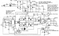
This is my copy, redesign of the K6 FWB, This supply is under test
and some part values or parts are subject to change. It operates in current mode and only the postive rail is regualted. While care was taken in drawing the schematic there might be errors, a word of caution.
chas
N-channel
This is my copy, redesign of the K6 FWB, This supply is under test
and some part values or parts are subject to change. It operates in current mode and only the postive rail is regualted. While care was taken in drawing the schematic there might be errors, a word of caution.
chas
Attachments
Szia Danko!
I have recently done a similar design based on the UC3856 controller IC. I was having similar problems: noises of various types and general instabilty. My design was also a full bridge, delivering about 500W.
The problem with the UC3856 and I suspect your controller is it's susceptibility to noise on the current sense pin. The 1k & 470pF filter help to remove some of this and the the UC3856 also has leading edge blanking that helps further. But with a resistive current sense circuit (R11) it will always be there in a high power supply and will always be a problem.
The controller terminates the switching cycle on a cycle-by-cycle basis and any noise present will terminate the cycle prematurely. The duty cycle will be observable fluctuating wildly. This is what produces the audible noise.
The only real solution is to use a current transformer in place of R11. This will instantly fix all your worries as if by magic! You may be able to use R11 & avoid the current sense pin picking up noise with very careful layout, but you may also waste many hours doing so.
I would also like to point out that a full bridge cannot run at more than 50% duty cycle. Therefore slope compensation isn't necessary. It can be added to offer slightly improved transient response if desired after the supply is stable and operating correctly.
Cheers, Ralph
Chas-
Design looks good. Ralphs99 raises some good points I didn't eveen think about. I noticed this same noise on my big 12V DC-DC (car amp). Whenever there was noise on the line (and the MC33025 can be noise-sensitive) there was noise at the outputs, too. Referring to the Slope Compensation Fig. 29A on the MC33025 datasheet, http://www.onsemi.com/pub/Collateral/MC34025-D.PDF it shows both noise-sensitive and nopise-immune slope compensation methods. Since you are using a emitter-follower to avoid loading down the C(t) pin of the '33025, you might want to check out the layout of these components and minimize the lengths of any traces tied to the transistor's base.
I noticed a couple of things on the output side: 1) I would connect the the opto sense network across the (+/-) outputs after the output inductors to eliminate the noise problem, and to maintain symmetry about the 0V line; 2) I also noticed some inconsistencies in the grounding symbology between primary-side and secondary-side grounds. The ground for the three-pin AC inlet should go to earth ground, and the negative side of the input recitfier bridge should be DC "Ground". I noticed they were tied together. This will let the magic smoke out of the two negative diodes. Also, I would tie the 0V output to the AC Earth ground. This might reduce the noise some. What the heck, can't hurt trying! OK, I'm rattling on, but this is just my two cents worth. I would be interested in seeing the waveforms. Other than that, good work, and I can't wait to see the finished product!
😎
Design looks good. Ralphs99 raises some good points I didn't eveen think about. I noticed this same noise on my big 12V DC-DC (car amp). Whenever there was noise on the line (and the MC33025 can be noise-sensitive) there was noise at the outputs, too. Referring to the Slope Compensation Fig. 29A on the MC33025 datasheet, http://www.onsemi.com/pub/Collateral/MC34025-D.PDF it shows both noise-sensitive and nopise-immune slope compensation methods. Since you are using a emitter-follower to avoid loading down the C(t) pin of the '33025, you might want to check out the layout of these components and minimize the lengths of any traces tied to the transistor's base.
I noticed a couple of things on the output side: 1) I would connect the the opto sense network across the (+/-) outputs after the output inductors to eliminate the noise problem, and to maintain symmetry about the 0V line; 2) I also noticed some inconsistencies in the grounding symbology between primary-side and secondary-side grounds. The ground for the three-pin AC inlet should go to earth ground, and the negative side of the input recitfier bridge should be DC "Ground". I noticed they were tied together. This will let the magic smoke out
of the two negative diodes. Also, I would tie the 0V output to the AC Earth ground. This might reduce the noise some. What the heck, can't hurt trying! OK, I'm rattling on, but this is just my two cents worth. I would be interested in seeing the waveforms. Other than that, good work, and I can't wait to see the finished product!😎
connection of feedback
N-channel thanks for the input, the feedback as shown is wrong and there might be other errors since this is the orginal print. Point on the grounding well taken. Ralph's comments were for Danko not this design and I have looked at the datasheet for 33025 and noticed exactly what both of you are in reference to. At present I am fine tuning startup circuit and gate driver circuit.
chas
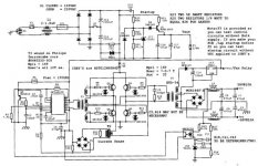
Three comments on the start-up ckt: 1) I like the way you use a TL-431 for the transistor's reference, and 2) I like the fuse coming off the output of the start-up ckt to the Vcc-pin of the PWM chip, and 3) I like how the 1mF cap on top of the 82kW resistor lets the start-up ckt stay on only for about a second or two. Nice work!
Startup circuit
N-channel
The startup circuit is from an TI app note (slua373),title "Bootstrap circuit for green mode applications " and works with VDC's from 120 to 375 with values in the schematic it's on for about 400 msec. Placement of the fuse is my idea to be able to troubleshoot and test supply.
chas
N-channel
The startup circuit is from an TI app note (slua373),title "Bootstrap circuit for green mode applications " and works with VDC's from 120 to 375 with values in the schematic it's on for about 400 msec. Placement of the fuse is my idea to be able to troubleshoot and test supply.
chas
DO NOT DO THAT.As you can't connect digital gnd to signal gnd directly, so is here. You can't connect power(output)gnd to AC gnd.Think about that.Also, I would tie the 0V output to the AC Earth ground.
Szia ralphs99!
I will try to remove some noise from the CS pin of the UCC2808.
Are you hungarian? 🙂
I will try to remove some noise from the CS pin of the UCC2808.
Are you hungarian? 🙂
luka said:
DO NOT DO THAT.As you can't connect digital gnd to signal gnd directly, so is here. You can't connect power(output)gnd to AC gnd.Think about that.
Where not possible or practical to do this, AC bypassing to earth ground from the 0V output can be accomplished by running a 0.01mF cap in parallel with a 1MW resistor from 0V to earth ground.
Szia Danko,
I'm not, but my wife is Hungarian!
Be careful not to increase the value of the 470pF cap too much. 1nF is about the maximum you should try. Increasing it's value further disturbs the controller's ability to current limit; with sometimes spectacular results!!!
Cheers, Ralph
I'm not, but my wife is Hungarian!
Be careful not to increase the value of the 470pF cap too much. 1nF is about the maximum you should try. Increasing it's value further disturbs the controller's ability to current limit; with sometimes spectacular results!!!
Cheers, Ralph
Hello ralphs99!
Yes, if that capacitor is too high, then the current-ramp will be distorted, becouse of that R-C low-pass filter's too low breakpoint.
I'm going to try soldering a n*10pF ceramic capacitor to the CS and GND pin of the IC.
regards, Danko
Yes, if that capacitor is too high, then the current-ramp will be distorted, becouse of that R-C low-pass filter's too low breakpoint.
I'm going to try soldering a n*10pF ceramic capacitor to the CS and GND pin of the IC.
regards, Danko
N-Channel & chas1
About that Coupling cap, 1uF is too low value, so I will use 4.7uF.By doing so I will disregared safety and use only 63v one.Since this is more than enough in normal operation.
Will this be OK, if in case of error this will be the last thing that I would care about?
About that Coupling cap, 1uF is too low value, so I will use 4.7uF.By doing so I will disregared safety and use only 63v one.Since this is more than enough in normal operation.
Will this be OK, if in case of error this will be the last thing that I would care about?
coupling cap
Luka
The value of this cap can be determined by the following formula
C = 1 / (4 * 3.28)^2 * Fr ^2 *(Np/Ns) ^2 *L
Np = number of turns in primary
Ns = number of turns in secondary
Fr = resonant frequency kHz, use .25Fs
Fs = switching frequency
L = output inductor in uH
As you can see you need the value of the output filter inductor in uH.
After you perform the calculation then you can check for proper
operation at low Vin by the procedure below:
Calculate your Ic at low line
for example 200 watt output Ic for half-bridge
would be :
3*(200)/320 = 1.86A Ic
320 = normal voltage
Low line would be:
1.86 + .2(Ic)(1.86) = 2.3A
if cap has a value for example of .5uF and converter fs
is 50kHz then cap voltage would be:
VC = 2.3(20 x 10-6) / .5 x 10 -6 = 90V
As you can see this is too high and will effect the operation
of your supply.
Then you can re-calculate this value based on a 30 volt
charging value as N-channel posted in a previous post by the formula:
C = 2.3(20 x 10 -6) / 30 = 1.5uF
where in this example 50kHz is Fs and 1 / Fs = 20 x 10 -6
This example is from pg 31- 34 of " High Frequency Switching Power Supplies Theory & Design by George Chryssis"
If you have "Switching Power Design by Pressman" then refer to
pg. 97 and 98 for a simpler procedure to calculate this value.
If you look at your primary waveform during test you should see the tops remain flat and the pk- pk remains constant then flux walking is not your problem, for if it is you will notice your center line changing until saturation and smoke thereafter, however line and load changes will also effect this but this normally occurs after the supply is in operation and for no apparent reason the primary switches fail. flux walking could be the cause along with other things.
I think the value you have choosen is to high, you can always paralell two 1uF caps for a value of 2uF and I think this should be ok. A source for these caps is an ATX power supply, they are the brown caps across the input line filter of this type of supply.
If you don't mind re-stating the problem your are having with this supply because this thread has been rather long in tooth and maybe the problem's I have been addressing you have already resolved thru all the previous post by others.
chas
Re: Startup circuit
Doesn't it worry you that there is no isolation between output and input? If you ground the output you'll let out the magic smoke from the startup circuit. And if you don't you might let it out of yourself!
chas1 said:N-channel
The startup circuit is from an TI app note (slua373),title "Bootstrap circuit for green mode applications " and works with VDC's from 120 to 375 with values in the schematic it's on for about 400 msec. Placement of the fuse is my idea to be able to troubleshoot and test supply.
chas
Doesn't it worry you that there is no isolation between output and input? If you ground the output you'll let out the magic smoke from the startup circuit. And if you don't you might let it out of yourself!
chas1
I see that, but I cannot know the value of output inductor because:
1.)Don't have equipment to see inductance of output inductor
2.)Core is unknown, so there is no spec. for it
how would you check the value of it, with scope maybe?
I see that, but I cannot know the value of output inductor because:
1.)Don't have equipment to see inductance of output inductor
2.)Core is unknown, so there is no spec. for it
how would you check the value of it, with scope maybe?
value of inductor
Luka if you don't have a method to measure inductance there are circuits on the web that can be used in conjunction with a DVM to measure both cap & inductance or check out this URL
chas
[http://engr.nmsu.edu/~etti/fall96/electronics/induct/induct.html[/URL]
Luka if you don't have a method to measure inductance there are circuits on the web that can be used in conjunction with a DVM to measure both cap & inductance or check out this URL
chas
[http://engr.nmsu.edu/~etti/fall96/electronics/induct/induct.html[/URL]
- Home
- Amplifiers
- Power Supplies
- Offline full-bridge SMPS… need help