Let's wait until tomorrow, then we'll see, what to do, agreed?
Or you can send them like you did the first one.
Or you can send them like you did the first one.
Drawing
Chas-
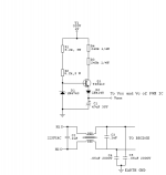
Thanks for drawing and posting the start-up ckt I described. Little error- swap the two 8.2kW's with the two 220kW's, otherwise the 13V Zener will smoke, and the TIP41 will never get enough current to power the IC. Also, the TIP41 is rated at only 100Vce, and you will surely let the magic smoke out if you power it up. The TIP50 is rated at 400Vce at 1A, 40W P(diss). Other than that, It looks great! 😀
Chas-
Thanks for drawing and posting the start-up ckt I described. Little error- swap the two 8.2kW's with the two 220kW's, otherwise the 13V Zener will smoke, and the TIP41 will never get enough current to power the IC. Also, the TIP41 is rated at only 100Vce, and you will surely let the magic smoke out
if you power it up. The TIP50 is rated at 400Vce at 1A, 40W P(diss). Other than that, It looks great! 😀correction
N-channel
I was trying to help, posted a drawing without checking .
here is the correct one
chas😱
N-channel
I was trying to help, posted a drawing without checking .
here is the correct one
chas😱
Where.......
......is it?
Chas,
I didn't mean for it to sound so.... snide? Would that be the right word? I really meant Thank You for posting the schemo. I don't know how to do it. Yet.
I was searching the smilies box for a blind smilie, and I've got to say, this is, by far, the best and funniest collection of smilies I have ever seen! Moderators: Keep up the great work. Sorry for the digression. 😎
Anyway, I concur with the values for the components in the common-mode AC Line filter.
Steve
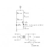
correct drawing
N-channel
I take no offense, I should have checked the drawing after all
someone might use the circuit and it should work.
luka
read the post by N-channel before you wire up circuit, the resistor values are wrong. resistors to base drive should be 2 240K 1/4 watt resistors, the collector of tip50 should be wired to the bulk supply(320Volts) thru 2 8.2k 5 watt resistors other than that the circuit should work.
chas
Attachments
schematic you posted & waveforms
luka
I looked at your schematic and the primary waveform, you indicated that the fsw was 50kHz with a 50v per div which indicates a 300 Vpk-pk across switches. Have you tested your supply with a load or your amp yet? If so what were the value of your output rails, ripple and also a waveform of your secondary side before the inductors would be nice. A audio power amplifier
power supply should be able to provide the required rail voltage
at light loads say around 200- 300ma so the bais currents can be set properly. Based on your location I assume your line voltage is
220VAC @50Hz. I would think that the primary waveform would be more than 300 Vpk-pk unless there is low input voltage or loss
in the switch. What is the bulk voltage value? If you have time could you post it.
Thanks
chas
Since I have calculated for wrong input voltage, I only have +/- 23V of DC,thus making it unregulated and this would be a bit low for some high power amp testing😀 , but I did put 8ohm resistor insted to that votage, so I did get 230w+.
That picture was taken during this load.
And yes there was actully 315 Vpk-pk across switches.
Lol ripple was about 8 Vpk-pk, but that was because output C were only 10uF🙄 with no output inductors.
Secondary waveform was perfect square as on primary.I don't have any picture of it sorry, and I can't take one now, because I have take it already apart for this version,the one we are talking about.
Jup my line voltage is 235VAC @50Hz.You are correct.
I have been using buz80 or something, rated 900V@4A with Rdson of 4ohm.Where is this bulk voltage?On main C? If so there was 165V across each.
Chas- No problem. The last circuit you posted is exactly the start-up circuit I used, even the 1N4743. As for heatsinking the TIP50, I would recommend it, since there can be as much as 367VDC across it, and as much as 30mA flowing thru it, it would be dissipating as much as 11W, even if for only a second or two. If the PWM IC should accidentally lock up on start-up, the TIP will be supplying 25mA for a long period, and this would certainly fry the TIP if left w/o a heatsink. Not a normal mode of operation, but good engineering safety practice.
Luka- for your power levels, you might want to use some MOSFETs with higher I(d), and lower Rds(on) to lower conduction losses a bit. I said I was gonna post the design procedure for the coupling cap on the main Xfmr, but I brainfarted and realized that book is at work, not here at home. When I get back Monday, I will lookit up and post it. FYI, it is in Chryssis' book, both the 1984 and 1989 editions.
Way back in 1994-5, when I did my first off-line half-bridge, I brok the SMPS up into six or seven modules: AC input line filter, HV rectifier/main filter, PWM Control w/opto feedback, driver tramsformers & HV MOSFETs, main transformer, and then the output section, consisting of 200V Schottkys, common-mode indictor, and Panasonic HFQ-series electrolytics. It powered a pair of 40W amps that I copied from an old Radio Shack car amplifier (I used to work there, and ordered every service manual with schematics for everything that had an audio amp- the boss was not happy 😡). The Amp sounded great, and there was absolutley no hiss on the outputs that I could hear. No switcher noise, although that could be because I had separated the PSU and the amps by shielding. Anywho,
The thing worked excellently, and I deeply regret having cannibalised the PSU for other projects, because for my first one to have worked so well, it would be a great converastion piece to have around.
the TIP if left w/o a heatsink. Not a normal mode of operation, but good engineering safety practice.Luka- for your power levels, you might want to use some MOSFETs with higher I(d), and lower Rds(on) to lower conduction losses a bit. I said I was gonna post the design procedure for the coupling cap on the main Xfmr, but I brainfarted and realized that book is at work, not here at home. When I get back Monday, I will lookit up and post it. FYI, it is in Chryssis' book, both the 1984 and 1989 editions.
Way back in 1994-5, when I did my first off-line half-bridge, I brok the SMPS up into six or seven modules: AC input line filter, HV rectifier/main filter, PWM Control w/opto feedback, driver tramsformers & HV MOSFETs, main transformer, and then the output section, consisting of 200V Schottkys, common-mode indictor, and Panasonic HFQ-series electrolytics. It powered a pair of 40W amps that I copied from an old Radio Shack car amplifier (I used to work there, and ordered every service manual with schematics for everything that had an audio amp- the boss was not happy 😡). The Amp sounded great, and there was absolutley no hiss on the outputs that I could hear. No switcher noise, although that could be because I had separated the PSU and the amps by shielding. Anywho,
The thing worked excellently, and I deeply regret having cannibalised the PSU for other projects, because for my first one to have worked so well, it would be a great converastion piece to have around.
I would just like to point out that there are some tricks to get very low power dissipation in the startup circuit. For example, a capacitor of suitable value can be charged through a resistor with 1mA or so until it reaches 15V or 20V, and then it can be switched to the supply rail of the control circuit.
N-Channel
Eva
I am planning on using mtw24n40 that i've got,later on irfp450.Luka- for your power levels, you might want to use some MOSFETs with higher I(d), and lower Rds(on) to lower conduction losses a bit.
Take your time🙂I said I was gonna post the design procedure for the coupling cap on the main Xfmr, but I brainfarted and realized that book is at work, not here at home. When I get back Monday, I will lookit up and post it.
Eva
How would you that? Maybe with triak?For example, a capacitor of suitable value can be charged through a resistor with 1mA or so until it reaches 15V or 20V, and then it can be switched to the supply rail of the control circuit.
mosfets
luka
If I were you I would follow the advice I think Eva posted about mosfets and find an igbt, good ones are the warp speed series from IRF or HGTG series from Fairchild. These devices are designed for SMPS work and other high frequency switching applications and the cost is about the same , I have seen them on ebay for about 3.00 dollars each. I realize the shipping cost to your country might be more than the cost of the device but in the end it might be worth it. I have just changed out a complete bridge of IRF450's for the HGTG12N60A4D and replaced the PWM chip with a MC33025P in current mode and I am in the testing phase. The bridge is designed for 2kW.
chas
luka
here is a link to a pdf file you might find helpful
[http://www.its.caltech.edu/~mmic/reshpubindex/papers/buckwalter.pdf[/URL]
chas
here is a link to a pdf file you might find helpful
[http://www.its.caltech.edu/~mmic/reshpubindex/papers/buckwalter.pdf[/URL]
chas
Nice supply .Thx for the link🙂. How is your 2kw supply coming along?Will you be able to share it, when fully complited?
Do you have any D class amp?
.Thx for the link🙂. How is your 2kw supply coming along?Will you be able to share it, when fully complited?Do you have any D class amp?
Luka
The FWB that I am modifying is not my design but I will share all with anyone including the schematics of changes, I am changing it from a voltage control to current control, replacing the SG3525 with a MC33025, replacing the IRF450's with igbt's and making small changes to the feedback loop. This supply was designed and published by Reinhard Metz and Myzil Boyce in an out of print magazine "Electronic's Now" I have provided the link to the files for this supply below. Reinhard Metz is a member of this forum and his design has been mentioned in previous post and on his site you will find excellent documentation. My amp is not a class d
but a new design of a class AB of 200 watts which can be scaled to 1kW, I have configured my bi-amp system as 300 watt sub, 200 watt mid and 100 watt for the high's. this is the reason for the supply. My current plans are to house the amps plus the supply in the speaker tower and to couple them with fiber optics, no cables. I also have a PFC designed and waiting for the controller chips and PCB.
I think you might want to recaluate your transformer IMHOP. The turns seem a liitle high for HalfBridge.
chas
http://www.a-and-t-labs.com/K6_Sw_Amp/index.htm
Yes I know what you mean. The reason for that is that later on I will change the zener diode's and go with +/- 60V for non-designed yet D-amp. I was wondering if you could help me with it?(After I'll have working smps)
Luka- Good on the 500V IRFP450's, they will enable the use of PFC later.
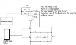
Chas- the last schematic you show is for a buck regulator using upper and lower MOSFETs, and not a true half-bridge, though the two look very much alike. I say this because it looks like you are taking feedback directly from one end of the main power transformer's primary winding. Of course, if this is a block diagram, not completely representative of the whole circuit, then I would stand corrected. 😉 Oh fudge! I just went back and actually read your last post the schemo was attached to, and you clearly state "voltage control buck regulators", so I do indeed stand corrected. Never mind!
I do like the fact that you're upgrading the '3525 to the '33025. While the 3525 is a good chip, and can even be used in current-mode (with an op-amp driving the shut-down pin), it is not as robust as the 33025, and lacks the benefit of the additional research that went into designing the '33025. How will you make this change? Did you make a smaller, separate board for the controller section? This is what I plan to do for my next SMPS. Actually, it will be a dual PWM, so I will synch a slave MC33025 to a master '33025 so I can have separate left & right supplies with separate regulation, with no beat frequencies, and the ability to add Active PFC'ing later on. I have a couple of rails of old Motorola MTW20N50e's laying around, so I guard these jealously and use them sparingly! I do wish ONSemi would get back into the high-voltage MOSFET business again. 🙁
I have opto feedback in my designe.
N-Channel
You said
N-Channel
You said
which you use.But I don't see how can supply 100mA, with 2x 8.2k ohm between Vbus and the '50's Collector. (330v - 12v/2x8.2k=19.2mA) Shouldn't be there only 1k ohm?2) Have you simulated the start-up circuit? I realise that it operates for only a second or two, but Brown uses a "highly starved" linear regulator consisting of a TIP50 (400V NPN), 1KW between Vbus and the '50's Collector, with a 440k W resistor srting feeding a 13V zener diode. Also, since the 3525's start-=up current is also its operating current, having over 100mA capacity will help to ensure that the '3525 gets enough power at start-up so it doesn't lock up.
- Home
- Amplifiers
- Power Supplies
- Offline full-bridge SMPS… need help