Luka
This type of feedback will not compensate the supply and therefore it will not regulate correctly. This loop is critical and must be compensated wether you use optoisolation or not and this is the most difficult part of the design especially if you are going to use it to power an audio amplifier which is a complex load. However you can strap the 3525 for 50% duty cycle, remove the inductors, redesign the transformer so when your rails are loaded you have the correct voltage and it is stiff enough for bass transients. Crown and others use this, referred as unregulated operation.
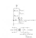
The idea of the startup circuit is to supply up to 15ma so the PWM chip will start. This done by the 47uF bulk cap and the circuit I posted is designed for the MC33025 but should work for the 3535.
If you refer to the schematic I posted this is how the values are derived:
R1 = R1 & R2 in the print R1= Vin (min) 252 to 300volts - Vzener/ Izener(min)
R2 = R4 & R3 = Vin(min) - Vzener/ Istart
The transitor is choosen with a VCE >> Vin(max)
I have simulated this circuit and it's output is about 11.0 volts allowing for emitter-base diode drop + the 1n914 drop 13.0 - 1.4
with a startup current of 10 ma. the reason there are two resistors for R1 & R2 is safety (voltage breakdown). This information is from Marty Brown's book and not mine.
I have not confirmed that this is sufficent for Sg3525 startup.
If you can you should aquire a copy of Marty Brown's book, it has a lot of examples of every part of SMPS design and covers all topologies including PFC and most important how to compensate a SMPS properly.
chas
This type of feedback will not compensate the supply and therefore it will not regulate correctly. This loop is critical and must be compensated wether you use optoisolation or not and this is the most difficult part of the design especially if you are going to use it to power an audio amplifier which is a complex load. However you can strap the 3525 for 50% duty cycle, remove the inductors, redesign the transformer so when your rails are loaded you have the correct voltage and it is stiff enough for bass transients. Crown and others use this, referred as unregulated operation.
The idea of the startup circuit is to supply up to 15ma so the PWM chip will start. This done by the 47uF bulk cap and the circuit I posted is designed for the MC33025 but should work for the 3535.
If you refer to the schematic I posted this is how the values are derived:
R1 = R1 & R2 in the print R1= Vin (min) 252 to 300volts - Vzener/ Izener(min)
R2 = R4 & R3 = Vin(min) - Vzener/ Istart
The transitor is choosen with a VCE >> Vin(max)
I have simulated this circuit and it's output is about 11.0 volts allowing for emitter-base diode drop + the 1n914 drop 13.0 - 1.4
with a startup current of 10 ma. the reason there are two resistors for R1 & R2 is safety (voltage breakdown). This information is from Marty Brown's book and not mine.
I have not confirmed that this is sufficent for Sg3525 startup.
If you can you should aquire a copy of Marty Brown's book, it has a lot of examples of every part of SMPS design and covers all topologies including PFC and most important how to compensate a SMPS properly.
chas
Attachments
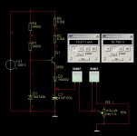
Block Diagram
N-channel
This was only intended as a block diagram to indicate a method of closing the feedback loop using type III compensation. In MHOP this has been ommited in Luka's design.
chas
N-channel
This was only intended as a block diagram to indicate a method of closing the feedback loop using type III compensation. In MHOP this has been ommited in Luka's design.
chas
I've got my hands on these books:
Abraham I. Pressman - Switching Power Supply Design 2nd ED
Marty Brown's book - don't remember the title and
Chryssis' book - don't remember the title
Very good books!!🙂
So you can say where/what exactlly to look for.
Supply current for SG3525 is 14(20mA-max)@35v and less than 1mA for IR2110
At home I have simulated start-up circuit that had two TIP50 in series.First was set to drop bulk voltage down to 165, then the other one drop voltage down to the one needed (12-15v).
Compensation
Luka- I agree. BTW, I went back and recalculated my #'s for the 2 - 8.2kW 5W resistors. You are right in that, at low line, it is good for just about 20mA. Duh!
Having gone back and re-read the datasheets from ONSemi for both the SG3525 and the MC33025, the big difference in the start-up is that the '33025's start-up current is something like 500mA and its operating current is 25-35mA. By contrast, the '3525's start-up current is its full operating current, 14-20mA. Therefore, this start-up circuit is mandatory for the SG3525, but you could get away with just the high-value resistor to charge the 47mF capacitor, but the "highly-starved" linear regulator gives better control of the start-up process.
Chas- I concur with Luka in that compensating your feedback is so important because it determines response time of your system to changing conditions. Marty Brown's book has many good design examples of all stages of the SMSP, and feedback compensation is covered in great detail. I use his book in determining the type if feedback network to use, depending on the topology, method of control, etc.
That would be our high line, not low🙂Luka- I agree. BTW, I went back and recalculated my #'s for the 2 - 8.2kW 5W resistors. You are right in that, at low line, it is good for just about 20mA. Duh!
And that is the circuit...
Attachments
Man! I gotta stop posting when I should be 😴'ing! Really need the coffee today. I wil lgo back and re-read Brown's section on start-up ckts.
Luka- I never thought of cascoding the TIP50s for increased current capacity. Looks interesting. Tested it yet, or just simulated?
Danko- Unitrode (now a division of TI) sample me a few SIOC samples of the UCC2808 a few years ago (asked for the '1808, but these are for sale only), but I haven't had the the ability to play with them, yet. Once I learn the ins-and-outs of ExpressPCB, I plan to have a couple of boards made for testing. Datasheets look promising. Ideal App for this would be DC-DC for car amp, or for laptop DC-DC (12 to 19V) booster.
Man! I gotta stop posting when I should be 😴'ing! Really need the coffee today! I will go back and re-read Brown's section on start-up ckts.
Luka- I never thought of cascoding the TIP50s for increased current capacity. Looks interesting. Tested it yet, or just simulated?
Danko- Unitrode (now a division of TI) sample me a few SIOC samples of the UCC2808 a few years ago (asked for the '1808, but these are for sale only), but I haven't had the the ability to play with them, yet. Once I learn the ins-and-outs of ExpressPCB, I plan to have a couple of boards made for testing. Datasheets look promising. Ideal App for this would be DC-DC for car amp, or for laptop DC-DC (12 to 19V) booster.
N-Channel
No, I have only simulated it, but there is no reason why it woldn't
work, but you never know until you test it.
No, I have only simulated it, but there is no reason why it woldn't
work, but you never know until you test it.
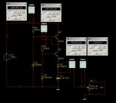
N-channel: I'm trying to make an SMPS with this IC, but I can't make it stable. The output voltage is stable. But the powersupply is beeeeeeping, end hissss -ing, and makes high frequency noises. The slope compensation isn't good (which is must) in current mode supplies, where the duty cycle is over 50%.
I tried to design from an Unitrode seminar's paper, but that didn't worked. I tried to set it with a trim.pot, but I couldn't "kill" that noise....
I tried to design from an Unitrode seminar's paper, but that didn't worked. I tried to set it with a trim.pot, but I couldn't "kill" that noise....
Danko,
This is a common problem with current-mode supplies. A little help from the timing cap C(t), with an emitter-follower current buffer can add some current to the current sense (cs) pin to compensate for this instability.
This is a quote from p.4 of the Unitrode UCC1808 / 2808 / 3808 datasheet, "Since the UCC3808 is a peak current-mode controller, the 2N2222A emmitter following amplifier (buffers the CT wave-form) provides slope compensation, which is necessary for duty ratios greater than 50%."
I did a current-mode controller based on the UC1846 a few years back, and I used this same trick, which stabilized the supply considerably. I, too, had the hissing sound coming from the main transformer. Adding an output inductor and slope compensation quieted it down, and removed the switcher noise almost entirely.
I have placed those components on the PCB, but that doesn't help :-(
Here's the schematic:
http://sziget.mine.nu/~danko/aramkor/gkrellShoot_07-30-06_161557.png
Here's the schematic:
http://sziget.mine.nu/~danko/aramkor/gkrellShoot_07-30-06_161557.png
Compensation
For what's its worth it seems that you are regulating both rails thru an opto device without any compensation and I would also check my grounds. Even with current control you have two loops to be concerned with. Would you mind posting your load requirement, I see your output caps are rated at 50 and 36 Volts, have you scope the output with no load, also what kind of core set are you using if it is an etd type the spring clips are not sufficent you should bond them with something.
chas
Danko-
Also, try putting an R-C Snubber across the primary of the transformer, like in AT/ATX PSU.
Also, try putting an R-C Snubber across the primary of the transformer, like in AT/ATX PSU.
Coupling Capacitor Value
I finally found my design procedure for calculating the value of this cap. It is an adaptation of Chryssis' procedure from the 1989 edition of his book.
C(c) = (I(max) * dT) / dVC(c),
For I(max) = 1.2 I(drain),
dT = capacitor's charging time, and
dVC(c) = Coupling Capacitor Ripple Voltage
So, for a ripple voltage of, say, 30V, an I(max) if 3.5A, and a charge time of 16.67uS, we get the following:
C(c) = (4.2A * 16.67uS) / (30V) = 0.0000023388F, or 2.33uF. Next standard value is 2.2uF, so use a 2.2uF rated at 250VDC.
yes I have found that section that is talking about Cc.You said that I should use 2uF, for 600w(aprox.) at 50kHz.Use 2x1uF parallel?
Parallel
Luka-
If you can't find a 2.2mF cap, then I think it would be OK to parallel 2- 1mf's. This might be pushing it, but if possible, try to get ones from the same production batch to ensure proper current-sharing.
Steve
Luka-
If you can't find a 2.2mF cap, then I think it would be OK to parallel 2- 1mf's. This might be pushing it, but if possible, try to get ones from the same production batch to ensure proper current-sharing.
Steve
coupling cap
When I attented a seminar sponsered by the author of the book you are in reference too, this subject was covered in depth because of the problems with using BJT's in bridge & halfbridge topology but when mosfets begin to replace them the flux imbalance became less of an issue and I have noticed that most designs simply have 2 small polyester film caps across each bulk cap and one end of the transformer tied to the center(refer to page 132 of Marty Brown's book) and T. McLyman Designing Magnetic Components for High Frequency dc - dc Converters(pg 415) These caps are 2 to 5uf 250VAC caps. Also I think to make the coupling cap calculation you need the value of the ouput inductor and I didn't see that indicated in the design in question, If I remeber correctly the equation mentioned is to evaluate the value of this cap to see if it interfere's with the regualtion at low line voltage. Also it was recomended to use a bank of caps if this value is high for the ESR(pg 31- 34).
chas
Chas,
I realized that MOSFETs' negative temp coefficient and ease of use as compared to BJTs made the issue of flux imbalance less of an issue, but I still include a coupling cap in series with the winding, just to be sure.
I have noticed that Brown does the 2 caps-in-series thing, and this is good, but, if a charge imbalance between the two caps should ever occur, then the issue of flux imbalance returns. Unless I am wrong, because I have not simulated one layout -v- the other. However, and I can't remember where I read this, perhaps Chryssis or Pressman, I'm not sure, but I thought they said that it is still a good idea to maintain a coupling cap to address all possibilities of flux-imbalance.
If this is indeed the case of two caps in series, with one end of the primary tied there, and the other end to the MOSFTEs, then in almost every half-bridge, the two bulk caps could be replaces with a single 400V or 450V bulk cap, cutting the cost on a whole lot of designs. Also for us DIYers, it makes doing our SMPSs that much easier, too.
I think I need to look further into this very interesting aspect of the overall SMPS design. 😎
- Home
- Amplifiers
- Power Supplies
- Offline full-bridge SMPS… need help