Snubber
Luka
If you are using 75 kHz for fsw, you might try 1000 pF in series with 50 ohm 10 watt resistor across transformer primary.
chas1
Luka
If you are using 75 kHz for fsw, you might try 1000 pF in series with 50 ohm 10 watt resistor across transformer primary.
chas1
Hi
What if Fsw is 50kHz? Is there a way to calculate this, even if you don't know primary inductance of transformer?
What if Fsw is 50kHz? Is there a way to calculate this, even if you don't know primary inductance of transformer?
snubber
Luka, yes you can solve the equation for any frequency see Brown's book or if you like estimate a value for your transformer leakage inductance and use the formula in the pdf file.
chas1
Luka, yes you can solve the equation for any frequency see Brown's book or if you like estimate a value for your transformer leakage inductance and use the formula in the pdf file.
chas1
Hi
I will try and use 3.3nF and ~40 ohms. That will give -29.1dB at 23MHz. Is that good enought?
I will try and use 3.3nF and ~40 ohms. That will give -29.1dB at 23MHz. Is that good enought?
Snubber
Luka
Try it and scope the results, the resistor value I gave you should be close for a broad frequency range just play with the cap value. you might want to go top Ridley's website and read the method he recommends for the same thing. After you make the change post scope results.
chas1
Luka
Try it and scope the results, the resistor value I gave you should be close for a broad frequency range just play with the cap value. you might want to go top Ridley's website and read the method he recommends for the same thing. After you make the change post scope results.
chas1
snubbers & Power 4-5-6
Luka
Download Power 4-5-6 from Ridley's engineering website it has a snubber calculator as part of the XLS spreadsheet. Note: You must have MS Excel installed to use this spreadsheet. I would not worry about secondary snubber's until you finish with primary first then I think you will see the secondary does not require a snubber. The demo is free.
chas1
Power 4-5-6
Luka
My mistake, I didn't try this software nor any of its features until now. It will not let you enter your values, these are default values and can't be changed. I will calculate a snubber based on the info you have provided.
chas1
Luka
My mistake, I didn't try this software nor any of its features until now. It will not let you enter your values, these are default values and can't be changed. I will calculate a snubber based on the info you have provided.
chas1
Hi
This is original waveform with no snubber
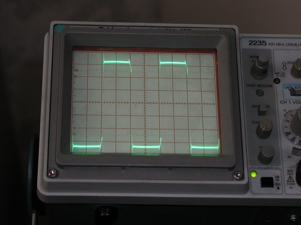
Then I've put snubber on. It is made of 3.3nF and 89 ohms. That 3.3nF is way better then other caps that I have here, it is also really big for 3.3n, but all it is writen on is (3.3 k 4 and below that w6c and simbol of company that makes it)
This is how it looks with it
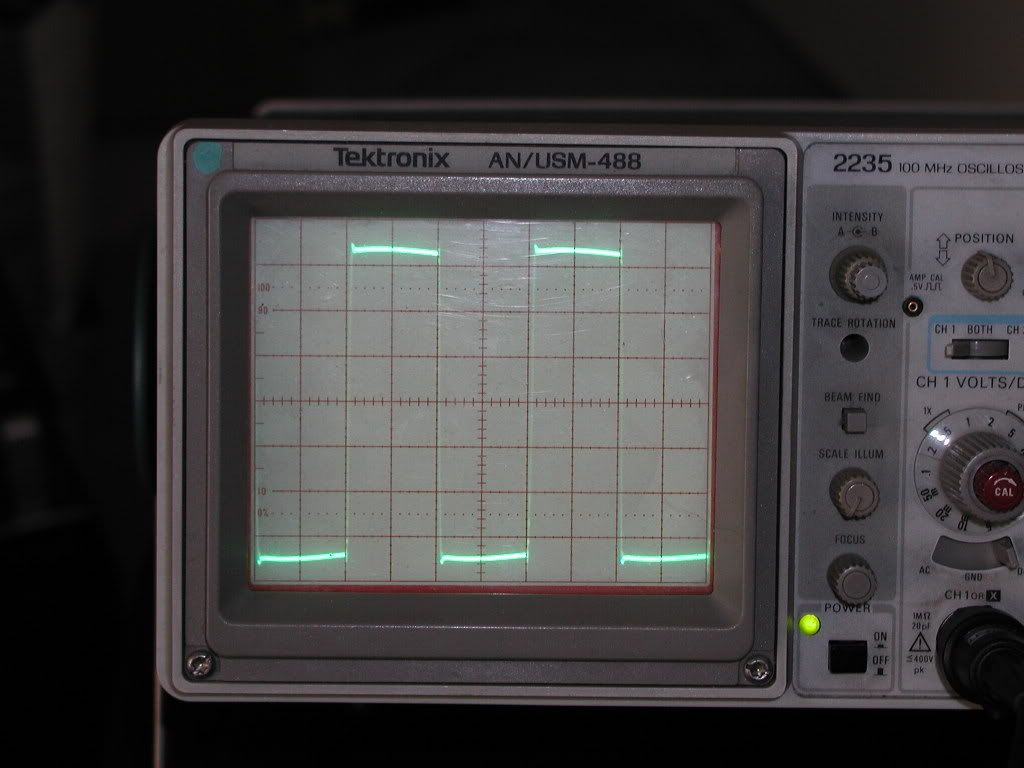
What do you think, is that good enought?
This is original waveform with no snubber
Then I've put snubber on. It is made of 3.3nF and 89 ohms. That 3.3nF is way better then other caps that I have here, it is also really big for 3.3n, but all it is writen on is (3.3 k 4 and below that w6c and simbol of company that makes it)
This is how it looks with it
What do you think, is that good enought?
snubber
Luka
Is this waveform taken across the primary, I don't see any deadtime. what about the waveform of the gate to source and also the waveform at the diode before the inductor. However I think that you have snubbed the switches correctly, I see no excessive ringing.
chas1
Luka
Is this waveform taken across the primary, I don't see any deadtime. what about the waveform of the gate to source and also the waveform at the diode before the inductor. However I think that you have snubbed the switches correctly, I see no excessive ringing.
chas1
Hi
I never did see dead time in half bridge, those pic were taken with gnd of probe being connected to mid point of input caps and + on the other sire of primary, but that doesn't mean that there isn't one.
This is looking at both gates at the same time.
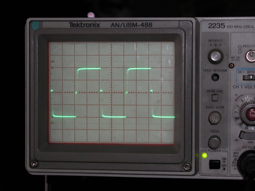
I never did see dead time in half bridge, those pic were taken with gnd of probe being connected to mid point of input caps and + on the other sire of primary, but that doesn't mean that there isn't one.
This is looking at both gates at the same time.
deadtime
Luka
Now I see the deadtime, nice clean gate drive are you using a gate driver IC.
chas1
Luka
Now I see the deadtime, nice clean gate drive are you using a gate driver IC.
chas1
Hi
Jup IR makes greatest gate drives for my needs, if I make it work (supply) with toroid, maybe I will try with gate trafo but until then IR will serve for this job.
I see no reason why sometime next week I won't be able to make new board, that will have start-up (finally 🙂) , and other as importing things
Feedback
Luka
I will post feedback circuit later today all I need to do is simulate it and change components to std. values. I don't understand why you would want to change to a toroid core, it has no advantages and shielding is going to be a problem. (explain)
chas1
Luka
I will post feedback circuit later today all I need to do is simulate it and change components to std. values. I don't understand why you would want to change to a toroid core, it has no advantages and shielding is going to be a problem. (explain)
chas1
Hi
This is more a test then anything else. My ultimate goal is to make supply powerfull enought to supply two d-amps with 1kw to 1.5kw. This is impossible if I would try to make it with ETD core.
The problem is that I can't put bigger core then ETD44 in to 1HE, that is just over 4cm in hight. Maybe ETD49 would still go. With toroids this isn't problem because they aren't very high. I will use ETD if possible, but to achieve my goal, this is a bit hard. I don't want go crazy with high freq., so I don't see any other possibility, unless I would build two of them.
What do you think?
class d amps
Luka
What class d amps do you have in mind, ETD-49 core sets can handle about 1.2kW@50kHz and 1.5kW@75kHz. This is the core set I use with no problems. The other is you can build 2 supplies with ETD-44 core set and sync the SG3525 this is easy to do.
chas1
Luka
What class d amps do you have in mind, ETD-49 core sets can handle about 1.2kW@50kHz and 1.5kW@75kHz. This is the core set I use with no problems. The other is you can build 2 supplies with ETD-44 core set and sync the SG3525 this is easy to do.
chas1
- Home
- Amplifiers
- Power Supplies
- Offline full-bridge SMPS… need help