Hi
So if I put one more primary over secondarys in parallel, like on page #125 in Marty Brown book, then it will be just like I would put 1/2pri, sec and 1/2 pri
So if I put one more primary over secondarys in parallel, like on page #125 in Marty Brown book, then it will be just like I would put 1/2pri, sec and 1/2 pri
Transformer Construction
Luka
Yes wind 1/2 primary and bifilar wind the secondary complete and then the other 1/2 primary. You have two secondary's one for the postive and one for the negative and they are tied together to form a center tap.
chas1
Luka
Yes wind 1/2 primary and bifilar wind the secondary complete and then the other 1/2 primary. You have two secondary's one for the postive and one for the negative and they are tied together to form a center tap.
chas1
Hi
Today I have rebuild whole trafo and done the next things:
-First I have put 19 turns(1/2) bifilar of primary
-Two secondarys each 7 turns trifilar
-And 16 turns of primary (ran out of wire, and space to wind it)
And the result is:
-75Vdc with no load (no FB)
-58.6Vdc onto 10.6 ohms
-47.xVdc onto 4 ohms
Things to do:
-A lot bigger input caps, coz 2x 390uF is not enough, but I don't know if I will be able to get 1000uF ones.
-Bigger output inductor would be probably better (20uH now)
-Coupling cap is now 1u+1u, replace it with 3x0.68u or something
-NEW board 🙂, this one had enough torching in her long life 😀
Hi
Maybe the wrong word used but by input caps I mean those big bulk 200v type caps. Now I have 390uF/400V ones in, wich take only a lot of place.
Maybe the wrong word used but by input caps I mean those big bulk 200v type caps. Now I have 390uF/400V ones in, wich take only a lot of place.
Hi
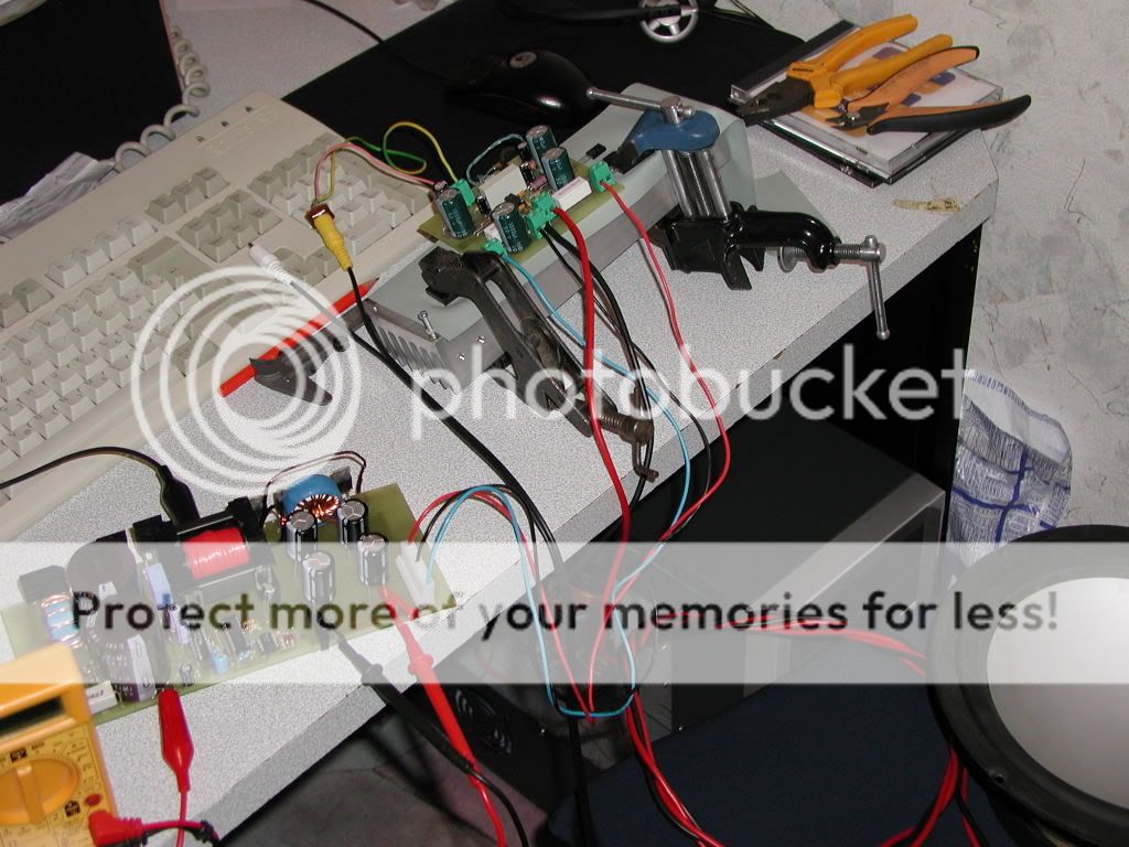
I have waited for so long this, so now it was time to connect it to amp.
And here is a pic of it
I have waited for so long this, so now it was time to connect it to amp.
And here is a pic of it
Heatsinks
Luka
Looks good but you might want to heatsink the power components of your supply before connection to a load.
chas1
Luka
Looks good but you might want to heatsink the power components of your supply before connection to a load.
chas1
I want to build a full bridge supply for plasma cutter that can plug into either 115 or 230. What's the best switching approach here? Transformer is out of the question, as I'm aiming for 15 A draw from mains (on either voltage) and I don't want a huge transformer.
Hi Chas
I know but it has crazy efficiency, running that amp, mosfets didn't even heat up, output diods did to about 50 if that.
This one will not see heatsink because I simply going to make new board for it, where I will change few things around SG and add start-up circuit, and change output layout completly because I designd it for too big caps. Apart from that, this might be all. Last thing will be to create a stable FB and here I will probably have some/a lot of troubles, hope not 🙂
Hi Nixie
Full bridge doesn't have that luxury where you can choose on what voltage it will run like in half bridge, so I have to ask what power do you need, coz 15A on 230v is a lot power.
It's only 3.5 kW. For a plasma cutter that's not a lot. My small air compressor already draws 15 A from the 115 V.luka said:Full bridge doesn't have that luxury where you can choose on what voltage it will run like in half bridge, so I have to ask what power do you need, coz 15A on 230v is a lot power.
I don't understand your comment about voltage. I can use two switching transformers and either switch their primaries in series or parallel depending on input voltage. If the bridge MOSFETs can handle the higher voltage, I don't see what the problem is.
Hi
Yes but it is simpler to change voltage in half bridge.
What output voltage/current will you need? Will it have to be ragulated? Good start would be to read Abraham Pressmans and Marty Browns and other books like that if you don't already know those things.If you do,...make prototype and test it if fits your needs.
I don't need regulation. That's adds unnecessary complexity. Output should be above 90 V at full load; open circuit if it goes to even twice that it's OK. When fed from a 230 V mains, should do over 35 A. Primary to secondary isolation should be better than 5 kV since an HV pulse is used to ignite the plasma.
Heatsink
Luka
I would heatsink the power components, Have you powered your amp with this supply and fed it with 30Hz to 15 kHz tones and also listen to any tracks for noise and artifacts. I would also scope outputs with a 30 Hz square wave for ringing. The reason for this I noticed you didn't wind any shields in constucting your transformer so Iwould expect some switching noise. Great Job!!
chas1
Plasma Cutter
Nixie
Take a look at the switcher used by the K6 amplifier at this URLhttp://www.a-and-t-labs.com with on slight mods should do what you want, I would use an ETD52 or ETD54 core set and set fsw to 100 kHz, forget the feedback and re-calculate the turns. If you run a ETD49 at 150 kHz you can get over 3kw but it would much easier to construct a tranformer with the larger core sets.
chas1
Hi
Thanks!
I didn't use generator yet, but I did listen to several tracks and there wasn't anything that would sound like noise or artifacts.Or my ears don't want to hear them at this point 😀. When there was no signal on input, amp was quiet like dead. There is no shield on trafo, only ground plate under him. The only thing that I saw with scope was 100Hz 5Vpp ripple under heavy load. In one week time I will start puting 4x 100w amp inside of enclosure, connect them to supply and play some music to see how supply performs.
I am also beginning to think that I should put on boad Aux +/- 12v power supply, for things like fans, bridgge adapter LEDs,...
How is your project comming along? Any big tests yet?
Ripple
Luka
Good
Ripple is close to norm, If you have no feedback when you add that you can decrease both high and low frequency ripple.
chas1
Luka
Good
Ripple is close to norm, If you have no feedback when you add that you can decrease both high and low frequency ripple.
chas1
Hi
I really don't think I will need that much power and also I would really like to put all in 1HE case, but it is something to think about.
How is your project comming along? Any big tests yet?
I really don't think I will need that much power and also I would really like to put all in 1HE case, but it is something to think about.
How is your project comming along? Any big tests yet?
Projects
Luka
I have finished all of my projects, the supply I stuck with is the HB voltage control and I used it for a tri-amp speaker system. I am now finishing up my website just a few loose ends to tie up.
chas1
Luka
I have finished all of my projects, the supply I stuck with is the HB voltage control and I used it for a tri-amp speaker system. I am now finishing up my website just a few loose ends to tie up.
chas1
Luka & Chas1
I haven't posted here in a while, but I stopped by to see how things were going.
Luka-
Your SMPS looks really good. You have given me a couple of good ideas for board layout. I have not had a chance to try the latest Scopemeter SW you sent. I hope to get to that this week. (Holding my breath! 😀 )
Chas-
How is your proj going? Any results/pics yet?
I am still working on modding an AT PC supply to put out +/-20V. Don't expect too much difficulty there- the board layout accommodates a C-L-C filter section for both the + and - rails (the former +5v & +12V sections). Most supplies' +12V have only an L-C filter after the big yellow cross-regulating toroid, without a cap, first. I never did understand this. :/ Will let you all know how it goes.
Cheers to all,
Steve
- Home
- Amplifiers
- Power Supplies
- Offline full-bridge SMPS… need help