Now I have a problem with feedback.As output reaches 2v pulses get narrower and turn of at some point over 2v. I don't think I did anything wrong
feedback
Luka
Use the test procedure in post # 432 as the output voltage rises the pulse should get wider until you reach regulation . If the feedback needs inversion use the other half of op amp as a follower. post schematic of what you have.
chas1
Luka
Use the test procedure in post # 432 as the output voltage rises the pulse should get wider until you reach regulation . If the feedback needs inversion use the other half of op amp as a follower. post schematic of what you have.
chas1
I can't understand how can be there only 0.5v on R3+R5 if supply voltage is 33v 😱 , and 1mA is going from + to TL
Fpr OPTO. I use 4n32 with 500% Ctrr
😱 , and 1mA is going from + to TLFpr OPTO. I use 4n32 with 500% Ctrr
Connections
Luka
Refer to pg#180-184 in Brown's book "Power Supply CookBook" the circuit is explained in detail,check all your connections. The value for the bais resistor for the Tl431 seems low to me should only allow about 10 ma . I need to check the data sheet for the
Tl431, 35 volts might be high for proper operation.
chas1
TL431A datasheet
Luka
Checked the datasheet for TL431A and based on that I will send you another design of the controller.
chas1
Luka
Checked the datasheet for TL431A and based on that I will send you another design of the controller.
chas1
Some how current was going into TL, regardless of resistor devider settings and at all times only 1mA.
eva?
eva,
please email me, your knowledge is invaluable to us diy'ers. i understand the issues for a professional like you, but i (we) would like you to continue with us.
thanks
eva,
please email me, your knowledge is invaluable to us diy'ers. i understand the issues for a professional like you, but i (we) would like you to continue with us.
thanks
Hi James
I'm not leaving, what I said is that from now on I will only discuss well known and popular SMPS topologies and I will keep any exotic high performance scheme for myself.
I'm not leaving, what I said is that from now on I will only discuss well known and popular SMPS topologies and I will keep any exotic high performance scheme for myself.
Hi Eva
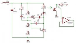
I never asked you what kind of feedback do you have. I think you one said 2pole-2zero, am I right? With what did you make it(OP or TL431, or something else)? If you any shema of it, that would be great.
Thanks, Luka
I never asked you what kind of feedback do you have. I think you one said 2pole-2zero, am I right? With what did you make it(OP or TL431, or something else)? If you any shema of it, that would be great.
Thanks, Luka
feedback loop
Luka
Happy Holidays, sorry I did not reply about feedback but I was tied up with my problems with my website but I will post a complete solution to your problem if you provide a schematic of your supply.
chas1
Luka
Happy Holidays, sorry I did not reply about feedback but I was tied up with my problems with my website but I will post a complete solution to your problem if you provide a schematic of your supply.
chas1
Happy Holidays to you to and everybody else, hope to see your webpage soon, as some solution to my problem, so I can play with it(smps) again.😀
Here you go
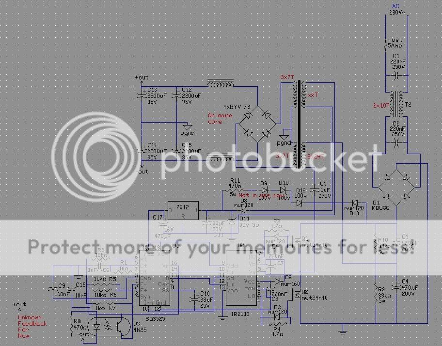
Fsw is 50k, output inductor 20uH each, on same core. I will have 2x2200uF for each rail
Fsw is 50k, output inductor 20uH each, on same core. I will have 2x2200uF for each rail
 to all.
I have some problems with sg3525, smps works fine, but after some time the sg becomes very hot end i must turn it of. I try to disconect the secondary traffo windings, after that sg stays cold. I think the 4 IRF840 can't eat so much.
Can you make any shema of how is your trafo connected to fet's.
Do you have cap. in series with primary of trafo connected to SG?
And if you use trafo you should have buffer to drive trafo instead of SG.
Do you have cap. in series with primary of trafo connected to SG?
And if you use trafo you should have buffer to drive trafo instead of SG.
I don't use cap, now i use buffer. Now sg stays cold, but power mosfets begin to warm, but not to much. The voltage voration become so hudge about 1-10V it's belogs from use power.
feedback
Luka
If you like you can breadboard this circuit and verify it will work with your design, the component calculations should be based on your gain requirements at the crossover frequency you choose. I don't understand why you have so much capacitance on your output rails it only complicates the feedback design I think two 1000 uF caps in each rail should be ok and then I would add .1 ohm resistor's in series with them and you could increase your crossover frequency with ease. With your current design I would cross at no higher that 5 kHz.
chas1
Attachments

- Home
- Amplifiers
- Power Supplies
- Offline full-bridge SMPS… need help