I am asking this because I have 200-250 Hz 5Vp-p sawtooth wave ripple at output that output caps just can't make a full DC out of it, so supply is constantly changing output D.C. because of this. I have 2x 39uH instead of 2x15uH or a bit higher, with 2x1000uF for each rail.
Luka,
Since these inductors are for filtering and not energy storage, I would recommend a bit lower inductance, say under 10uH. But, Hey! It's always worth giving your existing ones a try.
Steve
Since these inductors are for filtering and not energy storage, I would recommend a bit lower inductance, say under 10uH. But, Hey! It's always worth giving your existing ones a try.
Steve
I think that inductor is to big, not letting much high freq. to pass on to caps. They are there to be charged with high freq. not like in my case with low one.
luka said:I am asking this because I have 200-250 Hz 5Vp-p sawtooth wave ripple at output that output caps just can't make a full DC out of it, so supply is constantly changing output D.C. because of this. I have 2x 39uH instead of 2x15uH or a bit higher, with 2x1000uF for each rail.
This is a control loop problem. Your system is unstable and is oscillating a 200-250Hzm which is where the phase lag reaches 180º and is likely to be very close to the resonant frequency of your output filter too. Introduce a zero in the error amplifier response near 200-250hz and it should become stable. You will have to experiment a bit with R value from the zero RC in order to set a suitable "gain above the zero" (I'm assuming voltage mode control).
You should only see ripple at the switching frequency in the output if everything is right.
Inductor value
Luka
The flc of your output filter is about 570Hz, you will need to place a compensation network with two zero's at that frequency and then place a pole a decade from that 5700Hz and finally a pole about 1/2 fsw or a little higher. The gain should rise at a 20 db rate starting below 570Hz and proceed to a high value to reduce the low frequency ripple on your outputs, the high frequency rolloff will start about 1/2 fsw to reduce the high frequency ripple. I think if you do the math and place the right compensation for your supply in the feedback loop most of your problems will vanish. Since most of us don't have the equipment to measure the overall response of the feedback a spice plot along with trial and error will be necessary. The type of feedback you find for battery power supplies is not sufficent in most cases for offline SMPS. All that said the amplitude of your low frequency ripple seems high to me, scope the bulk supply and the cathode's of your postive output diodes. I think your transformer might have some winding issue's. A tip to help find problem is to operate supply unregulated and check your ripple if there is a large difference then the feedback might be your problem.
chas1
correction
Below is the error:
"The gain should rise at a 20 db rate starting below 570Hz and proceed to a high value to reduce the low frequency "
The correction is below
The gain should rise at a 20 db rate starting below 570Hz and proceed to a high value toward lower frequencies to reduce the low frequency ripple. You need at least 10db at double your line frequency.
chas1
I guess I will have to start thinking about using more complex feedback with op amp, but that was only matter of time. For now at this point I don't think I can do much more than lower inductance a bit.
 THANKS for all of your help till now
THANKS for all of your help till now Feedback
Luka
You will need some filter in your feedback, think of it as a tuned circuit you change the inductor the loop response changes and you end up with problems at another frequency. It should not be to hard to add a piggy back circuit on stand offs with an op amp and four components. You don't need +/- power for the op amp only +12 volts or what ever. The tl431 driving an opto coupler should work fine. Check out the Power Supply CookBook by Brown.
chas1
Feedback
Luka
You will need some filter in your feedback, think of it as a tuned circuit you change the inductor the loop response changes and you end up with problems at another frequency. It should not be to hard to add a piggy back circuit on stand offs with an op amp and four components. You don't need +/- power for the op amp only +12 volts or what ever. The tl431 driving an opto coupler should work fine. Check out the Power Supply CookBook by Brown.
chas1
Ok I'll do that first, before changing anything.
I don't see any op amp on page 132 of that book, where he builds halfbridge, just TL and few components
I don't see any op amp on page 132 of that book, where he builds halfbridge, just TL and few components
Re: Feedback
Post #408
Post #409
What, only twice? Come on now, one more... like they say, third time's the charm
Post #408
chas1 said:Luka
You will need some filter in your feedback, think of it as a tuned circuit you change the inductor the loop response changes and you end up with problems at another frequency. It should not be to hard to add a piggy back circuit on stand offs with an op amp and four components. You don't need +/- power for the op amp only +12 volts or what ever. The tl431 driving an opto coupler should work fine. Check out the Power Supply CookBook by Brown.
chas1
Post #409
chas1 said:Luka
You will need some filter in your feedback, think of it as a tuned circuit you change the inductor the loop response changes and you end up with problems at another frequency. It should not be to hard to add a piggy back circuit on stand offs with an op amp and four components. You don't need +/- power for the op amp only +12 volts or what ever. The tl431 driving an opto coupler should work fine. Check out the Power Supply CookBook by Brown.
chas1
What, only twice? Come on now, one more... like they say, third time's the charm
feedback
Luka
The supply on pg#132 uses current mode control and the circuit with the Tl431 is the outer feedback loop (voltage) and a type II pi controller. Your supply being a voltage mode control needs a type III controller which is described on pg#181 thru 184 and also the design is outlined on pg#216 thru 219. the major difference is the phase of the two types , with type II can get about 90 deg and the type III can be designed for about 180 deg of phase shift. This comes into to play as follows:
The LC output filter plus the op amp has low frequency poles which cause a 180 deg phase shift. We can ingnore the op amp pole for this example and therefore we have about 180 deg of phase shift at the corner frequency of the LC output filter. If we reach the crossover frequency and have a gain of 1 with a phase shift of 180 deg oscillations could begin or at any other frequency where this condition occurs. If you add two zero's to counter the poles at the LC corner frequency the phase shift will be reduced well below 180 deg then if you space two poles thru the higher frequencies you can shape your loop response to where you have a phase margin of 55 deg and sufficent gain in the low frequencies to reduce 120Hz ripple and reduced gain in the high frequencies so HF spikes with be attenuated.
So you see with a type III controller you have 2 poles and two zero's and in most cases makes it easy to tailor the response and for a type II controller you only have one pole and one zero and if the output filter caps have a very low ESR then it would be difficult to use this controller for voltage mode control IMHO.
The TL431 even though it is a precision Voltage regulator it is an op amp, check out the datasheet.
I think about 50 to 55 deg phase margin is a good design goal, although 40 to 45 deg is acceptable.
chas1
double post
Sorry for the double post, but was not intentional but a problem of fat fingers and power outage. Thanks for the kind reminder at least I hope it was.
chas1
Sorry for the double post, but was not intentional but a problem of fat fingers and power outage. Thanks for the kind reminder at least I hope it was.
chas1
How can I determine Fz(esr)=Fep1 and how the Fez1 or 2?
I have
Fsw= 50kHz
Adc= 5/24*0.95=0.188 <-- D.C. max
Gdc= -14.5
Fox= 9kHz
Fep2= 15kHz
I need to find out: Gxo,Fez1 and 2 or just Ffp,Fep1 which is Fz(esr), how to do that?
I have this two in parralel 1000uF/63v caps
I have
Fsw= 50kHz
Adc= 5/24*0.95=0.188 <-- D.C. max
Gdc= -14.5
Fox= 9kHz
Fep2= 15kHz
I need to find out: Gxo,Fez1 and 2 or just Ffp,Fep1 which is Fz(esr), how to do that?
I have this two in parralel 1000uF/63v caps
more info needed
Luka
The values you need are:
Control to output gain:
With the Sg3525 assume a 2.5 Volt ramp (Vc) and using max line
bulk supply (Vin) 380 VDC for EU the dc gain is about
20 log(10) (Vin / Vc) x (Ns / Np) where Ns = number secondary turns and Vp = number primary turns.
Np = 22 , Ns = 7, Vin = 380 and Vs = 2.5
= 20 log (380/2.5) x (7/22) = 33db or numeric 48
The modulator gain is the Flc / Fxo
I will use 32uH as inductor value and 2000 ufd as cap value
flc = 1 / 6.28 x SQR (32E-6 x 2000E-6) = 630Hz
your fxo = 9kHz therefore (630 /9E3) X 48 = mod gain = 3.4 or 1.5 db
A good value for (fesr) for most electrolytics is 2500 to 5000Hz pick the lowest 2500Hz. (place fep1 about here)
fep2 at 1/2 fs (50kHz).
You can plot the filter using a spice program (AC plot), a good free one is Tina-TI from the TI website and set the filter gain at 1.5db then cursor out to the fxo and read the gain needed to bring this up to a gain of zero. with that you can determine the values of the resistors.
If you plot just the filter using Tina -TI you will get an error " No op amp" just place an op amp symbol on the schematic with no connections and it will run fine.
I think your fxo is a little high I would go to about 5-6Khz.
I start like this I place my 2 zero's at Flc corner frequency then a pole at lowest fesr(2500hz) and the other pole a decade away 25kHz. I hope to get a 135 deg phase shift around my fxo. I breadboard this with my supply and check it . This works sometimes and sometimes I have to change the resistor values.
To convert db gain to numeric use 10^(db/20) where db is the value of db you want to convert , remember to use the minus sign if the db is negative.
I hope this helps if not I will send schematic.
chas1
Chas,
Thanks this helps me a lot. If there is not too much trouble please send me schematic also.
How to see if I get a 135 deg phase shift around my fxo ?
Thanks this helps me a lot. If there is not too much trouble please send me schematic also.
How to see if I get a 135 deg phase shift around my fxo ?
Tina-Ti
Luka
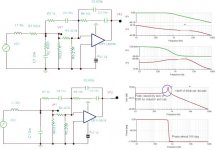
Yes both plots were done using Tina-TI. Some explanation about schematic, the top one has a resistor in series with the inductor and one in series with the cap ; the values are 100 mohm which are there to simulate ESR nothing else. The bottom one is the true schematic has no ESR shown and the plots are the real plots you will find when you plot this circuit. L1 and C1 are your FLC.
The schematic is not a design for your supply, it is just a type III controller circuit and is not applicable to your supply. The fxo is 4kHz and designed for FLC corner frequency of 1kHz and a DC gain of 12db and a mod gain of 0db or 1. Your case is different.
chas1
Luka
Yes both plots were done using Tina-TI. Some explanation about schematic, the top one has a resistor in series with the inductor and one in series with the cap ; the values are 100 mohm which are there to simulate ESR nothing else. The bottom one is the true schematic has no ESR shown and the plots are the real plots you will find when you plot this circuit. L1 and C1 are your FLC.
The schematic is not a design for your supply, it is just a type III controller circuit and is not applicable to your supply. The fxo is 4kHz and designed for FLC corner frequency of 1kHz and a DC gain of 12db and a mod gain of 0db or 1. Your case is different.
chas1
- Home
- Amplifiers
- Power Supplies
- Offline full-bridge SMPS… need help