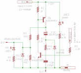
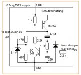
😉 hi all i found this protect schema on the web by schutzschaltung . i tried it and it works well with my smps .
but i wanted to increase the current limit to about 8 amperes or even 15 amperes . where can i adjust?? 🙁
but i wanted to increase the current limit to about 8 amperes or even 15 amperes . where can i adjust?? 🙁
Attachments

Hello,
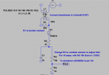
change R9 for lower value and/or increase 2.2k going to base of that transistor... build this par of circuit in LTspice and see what will work for you
change R9 for lower value and/or increase 2.2k going to base of that transistor... build this par of circuit in LTspice and see what will work for you
The resistor is the source of the mosfet at 15 amps represents a power loss that is not needed you should consider a current transformer in series with transformer primary,a simple circuit with a diode bridge and a split burden resistor should do nicely ,refer to Marty Browns book or check the web there are many.
Last edited:
thanks luka for the quick response .
r9 to be lowered to 0.01 from 0.1 and 2.2k to be raised to about 10k .
What is the limit now? Should be pretty high as is. And i woldn' t lower it that much, just a little bit, max to half the value (and not increase 2.2k at the same time).
If you do, you can live without this protection.
The resistor is the source of the mosfet at 15 amps represents a power loss that is not needed you should consider a current transformer in series with transformer primary,a simple circuit with a diode bridge and a split burden resistor should do nicely ,refer to Marty Browns book or check the web there are many.
hi chas 1 i once tried using current former , but with bad results .
because when there was overload yes it did shutdown. , but the output fets were getting hot , meaning that they were still conducting and also meaning you cannot leave it in the powersupply when failure occurs.
hi chas 1 i once tried using current former , but with bad results .
because when there was overload yes it did shutdown. , but the output fets were getting hot , meaning that they were still conducting and also meaning you cannot leave it in the powersupply when failure occurs.
If that's the case then something is wrong with design if you are using SG3525A pin 10 will shut the device down with 1 volt applied, there should be no output, I can refer you to a very simple circuit, not mine but should work. Marty Brown has simple design in book that will work and only uses 5 components.If you don't have book I will send you png.If you need pulse by pulse current monitor then MC34025P should be used.
Last edited:
Thanks luka and chas 1 . I am deeply greatful for the quick response and help.
Chas I am waiting for the png file.
Thanking you in advance. Steve
Chas I am waiting for the png file.
Thanking you in advance. Steve
Thanks I,ve downloaded the book , the link
https://archive.org/details/Power_Supply_Cookbook_2nd_Edition_By_Marty_Brown_Newnes_2001_278pp
https://archive.org/details/Power_Supply_Cookbook_2nd_Edition_By_Marty_Brown_Newnes_2001_278pp
That is the book, ref page 127, in middle of page is description of current limit then on page 132 is the actual circuit. I think there is a problem because when I simulate a coilcraft D1870 CT the current is not correct (D1870 is 1:100), do the math on pg 127 it is correct but LTspice does not agree I think I know and I am trying to make the correction, that is the big problem with this book it does have quite a few errors (equations verus circuit only).
😉 🙂 thanks chas 1 here are the files of the calculations of oc
Attachments
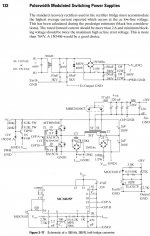
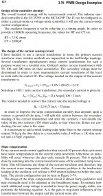
The calculations are based on the current value you choose for limit, he has chosen 3.1 amps, requiring a burden resistor of 75 ohms, but to get a grounded output he has added an addition resistor to the bridge and changed the value to 150 ohms and also changed the value of the burden resistor to realize a value of 75 ohms when the bridge diodes is conducting and you should get 1 volt eout which will shutdown control IC, in this case MC34025.
K6 FB SMPS revisit
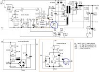
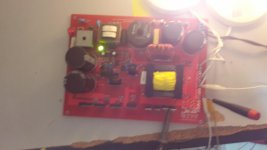
I have reworked the K6 smps and added IGBT switches and am in the process of testing the added features, one of them the regulation is from the positive rail,the controller is on the secondary side so I used the LM358 in a type III compensation to regulate both rails and also allow a variable output from 45 to 75 VDC into a 4 ohm load.Test have confirmed regulation and loop stability.
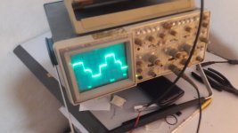
Still have some test to complete, as well as heat spreader design.I have included some pics.
The pcb layout while some is mine, however I did use some of the layout of Mr. Metz and I sent email asking his permission but received no response so I hope he understands.
I have reworked the K6 smps and added IGBT switches and am in the process of testing the added features, one of them the regulation is from the positive rail,the controller is on the secondary side so I used the LM358 in a type III compensation to regulate both rails and also allow a variable output from 45 to 75 VDC into a 4 ohm load.Test have confirmed regulation and loop stability.
Still have some test to complete, as well as heat spreader design.I have included some pics.
The pcb layout while some is mine, however I did use some of the layout of Mr. Metz and I sent email asking his permission but received no response so I hope he understands.
Attachments

Last edited:
Components
Luka Happy New Year, happy to see you monitor this thread.
Most components are from K6 parts lists except the output filter(caps and inductor),IGBT, and feedback circuit.
Step response is very good thanks to type III compensation, fsw (75kHz)
I will post LTspice simulation so you can play with it . all you will need to do is download LTspice(its free).
- Home
- Amplifiers
- Power Supplies
- Offline full-bridge SMPS… need help