hi Stewin
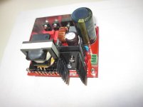
I attach schematic and PCB-Layout for your information.
-This prototype has been tested successfully with 200W continuous / 400W peak power feeding an IRS-board from Sure-Electronics and works nice since in 3 applications.
-It is short-time overload proof.
-Low-loss-softswitching is guaranteed over the full load range.
-gates are coupled capacitve achieving +/- 8V gate drive for best blocking
-this concept is restricted to half-bridge and cannot be extendet to full-bridge
-The main storage cap is definitely on the primary, large caps on the secondary are a no-go here.
-it could be a good idea to combine this with a PFC
-you need some special parts not easyly available: Resonant caps should be Wima MKP10 types, secondary elcos are polymere, and the transformer is a story of its own
-All in all this is what I could press on a double-sided PCB 80x100mm (free Eagle license)
Attachments
Last edited:
hi Stewin
I attach schematic and PCB-Layout for your information.
-This prototype has been tested successfully with 200W continuous / 400W peak power feeding an IRS-board from Sure-Electronics and works nice since in 3 applications.
-It is short-time overload proof.
-Low-loss-softswitching is guaranteed over the full load range.
You mean except for overload? I see no ZVS capacitor.
-gates are coupled capacitve achieving +/- 8V gate drive for best blocking
Why? I never experienced any problem with +12V/0V drive, and soft switching is especially not demanding. Traditional gate drive voltage has many benefits. If you need stronger discharge current, you'd better use a pnp transistor.
-this concept is restricted to half-bridge and cannot be extendet to full-bridge
Actually I did it. Not exactly full bridge, but 2 inverted phase half bridge, connected to 2 primary coils. Exact full bridge can be done also, but with secondary resonant caps.
-The main storage cap is definitely on the primary, large caps on the secondary are a no-go here.
Why? I do it all the time.
-it could be a good idea to combine this with a PFC
-you need some special parts not easyly available: Resonant caps should be Wima MKP10 types, secondary elcos are polymere, and the transformer is a story of its own
Any kind of polipropylene cap is OK, elcos can be standard if soft switching is really maintained. Yes, transformer needs some special knowledge, defined leakage and magnetising inductance and litz wire are required.
-All in all this is what I could press on a double-sided PCB 80x100mm (free Eagle license)
Nice work!
P.s.:
Why NCP1396B, if you don't use any feedback? Much simpler IR21531 can do this job perfectly! (Or if NCP1396B, then you could have designed stabilised PSU, with lower loss and protection.)
Attachments
Last edited:
You mean except for overload? I see no ZVS capacitor.
Why? I never experienced any problem with +12V/0V drive, and soft switching is especially not demanding. Traditional gate drive voltage has many benefits. If you need stronger discharge current, you'd better use a pnp transistor.
Actually I did it. Not exactly full bridge, but 2 inverted phase half bridge, connected to 2 primary coils. Exact full bridge can be done also, but with secondary resonant caps.
Why? I do it all the time.
Any kind of polipropylene cap is OK, elcos can be standard if soft switching is really maintained. Yes, transformer needs some special knowledge, defined leakage and magnetising inductance and litz wire are required.
Nice work!
P.s.:
Why NCP1396B, if you don't use any feedback? Much simpler IR21531 can do this job perfectly! (Or if NCP1396B, then you could have designed stabilised PSU, with lower loss and protection.)
As this converter works at constant resonant frequency, the magnetizing current of primary winding is constant over full load range, while the resonant tank current crosses zero during switching. With an appropriate dead-time the bridge-output toggles within constant-time and achieves ZVS, load independend. I did verify this and can provide scope screanshots as a proof of my claim.
Due to ZVS there a no strong demands concerning gate drive. Anyway I prefer this ac-coupling, because of higher blocking safety - and more than 8 pos gate drive do not make a significant difference concerning on-resistance of pow4r MOSFETs.
Choosing the controller was quite arbitrary, these ON-semi device were just at hand for me. Many others will do.
Concerning the resonant caps - I tested them under full load conditions, and some of them got hot or even exploded due to high ac-voltage load.
Why low capacitances on the secondary side?
It is a matter of reliabilty - with bigger caps the peak currents on 100/120Hz main voltage peaks increase the same way we know from conventional transformer supplies. Primary current peaks can rise substantially, destroying primary MOSFETs. I suspect this to be one of the dominant failure mechanisms of half-bridge offline converters.
Applying bigger caps using my LLC-converter will not be lethal due to inherent primary current limit - but it will suck your power reserve.
Another pro for the primary energy storage is size: One 330uF/400V stores at 300V the same energy as on 33.000uF at 30V.
When I fired the IRAUD-amps bought from sure-electronics I removed all these 1000uF caps and replaced them by 68uF/400V - these provide sufficient ac-ripple capacity. It takes a bit to accept this idea - but think of it.😉
As this converter works at constant resonant frequency, the magnetizing current of primary winding is constant over full load range, while the resonant tank current crosses zero during switching. With an appropriate dead-time the bridge-output toggles within constant-time and achieves ZVS, load independend. I did verify this and can provide scope screanshots as a proof of my claim.
This is true up to the point where current limiting diodes start to conduct, and make a phase lag. The higher the drop, the higher the current during switching.
Due to ZVS there a no strong demands concerning gate drive. Anyway I prefer this ac-coupling, because of higher blocking safety - and more than 8 pos gate drive do not make a significant difference concerning on-resistance of pow4r MOSFETs.
What is "8 pos"? Is "blocking safety" a real thing? Yes, in a PWM SMPS turning on one FET can charge somewhat other FETs gate via Crss, and you can prevent cross-conduction with negative bias, but this is an LLC converter, here positive dVds/dt only occures when you turn off the FET! Also some decades ago some IGBTs needed negative gate drive to switch off fast. But this is 2015 and you use very up-to-date components - in the old way.
Choosing the controller was quite arbitrary, these ON-semi device were just at hand for me. Many others will do.
Concerning the resonant caps - I tested them under full load conditions, and some of them got hot or even exploded due to high ac-voltage load.
I tested many (some dosens) also. All polipropilyene worked perfectly, and some poliethylene types also did the job (if oversized). This is what you can expect based on the characteristics of materials. Definitely NOT only MKP10 is usable.
Why low capacitances on the secondary side?
It is a matter of reliabilty - with bigger caps the peak currents on 100/120Hz main voltage peaks increase the same way we know from conventional transformer supplies. Primary current peaks can rise substantially, destroying primary MOSFETs.
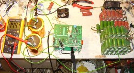
I thought. Then your circuit doesn't work well. If it worked properly, primary current couldn't rise so high that could destroy your enormously oversized MOSFETs. Trust me, I've built an SMPS with (truly) LLC topology which can put out 20A at 12V continuously, and 100 A at short circuit for 0.5 s in a closed plastic enclosure as big as a fist (case of a DeWalt 12V NiCd accumulator).
I suspect this to be one of the dominant failure mechanisms of half-bridge offline converters.
Only if there is no current limiting or badly designed in other way. Your topology is a proven concept for a long time, but you did some parameter wrong.
Applying bigger caps using my LLC-converter will not be lethal due to inherent primary current limit - but it will suck your power reserve.
??? I don't know what do you mean, but bigger cap on the output can actually serve the high pulse current needs of the amplifier without stressing power converter. In practice a 200 W PSU can serve a 200 W ClassD amp easily if there is a big cap between them.
"no go" <=> "not lethal" So what is your opinion really?
Another pro for the primary energy storage is size: One 330uF/400V stores at 300V the same energy as on 33.000uF at 30V.
Yes, this is true. However polimer capacitors are way more expensive, so maybe for the same price you can get much much bigger standard elcos. And additional caps between + and - rails can also increase efficiency.
When I fired the IRAUD-amps bought from sure-electronics I removed all these 1000uF caps and replaced them by 68uF/400V - these provide sufficient ac-ripple capacity. It takes a bit to accept this idea - but think of it.
Think about supply pumping and reactive power (of the speaker) also! If there is no, or very low capacitance, then what can stop rail voltages rising in these conditions?
Last edited:
This is true up to the point where current limiting diodes start to conduct, and make a phase lag. The higher the drop, the higher the current during switching.
What is "8 pos"? Is "blocking safety" a real thing? Yes, some decades ago some IGBTs needed negative gate drive to switch off fast. But this is 2015 and you use very up-to-date components - in the old way.
I tested many (some dosens) also. All polipropilyene worked perfectly, and some poliethylene types also did the job (if oversized). This is what you can expect based on the characteristics of materials. Definitely NOT only MKP10 is usable.
I thought. Then your circuit doesn't work well. If it worked properly, primary current couldn't rise so high that could destroy your enormously oversized MOSFETs. Trust me, I've built an SMPS with (truly) LLC topology which can put out 20A at 12V continuously, and 100 A at short circuit for 0.5 s in a closed plastic enclosure as big as a fist (case of a DeWalt 12V NiCd accumulator).
Only if there is no current limiting or badly designed in other way. Your topology is a proven concept for a long time, but you did some parameter wrong.
??? I don't know what do you mean, but bigger cap on the output can actually serve the high pulse current needs of the amplifier without stressing power converter. In practice a 200 W PSU can serve a 200 W ClassD amp easily if there is a big cap between them.
"no go" <=> "not lethal" So what is your opinion really?
Yes, this is true. However polimer capacitors are way more expensive, so maybe for the same price you can get much much bigger standard elcos. And additional caps between + and - rails can also increase efficiency.
Think about supply pumping and reactive power (of the speaker) also! If there is no, or very low capacitance, then what can stop rail voltages rising in these conditions?
Yes. limiting clamp diodes conducting is an overload condition - not normal operation. Normally only happening during power up.
8 pos was a typo, I meant 8V pos gate voltage. In fact the idea goes back to igbt drive considerations some time ago. Old concepts are not always obsolete - consider the aspect of drain-gate charge injections and the idea to build a negative charge barrier - specially in the case of MOSFETs with relativ high miller charge.
I do not claim that exclusively MKP10 are suitable - my sample list was small and cannot cover all types available on the market.
Not only do big secondary caps deliver pulse surges but they suck them from the converter as well, and that is the problem. I did some measurements and simulations with different sized secondary caps and it is evident that peak currents can rise far beyond safe operating area of my MOSFETs.
You are right, polymere are quite expensive at the time - but they save a lot of space and this is a hobby project after all. I can pay these easily by the saved money not buying audiophool caps. 😉
I do not claim this to be "bleeding edge" topology, but far better than many solutions you find on the market today. Bleeding edge was an 1kW/1MHzoffline LLC-converter half size of mine, published about ten years ago - utilizing transformer techniques far beyond my capabilities.
Bus pumping is another issue to be considered. It is evident that this converter fits exclusively to full bridge topologies, half bridge is a no go.
Big secondary caps are a no-go imho because the suck power reserve of my converter and may be lethal with some poor unprotected concepts found in the real world.
Last but not least please do clarify which parameters are wrong.
I choosed these MOSFETs mainly because the TO-247 case. TO-220 is a joke in high voltage high frequency applications. Btw this MOSFET works like a charm in this application.
Yes. limiting clamp diodes conducting is an overload condition - not normal operation. Normally only happening during power up.
Switching on is normal thing. OK, you call it abnormal. Does it change anything? It happens regularly, must work properly, especially if you tell that output cap is limited to very small value this because.
In fact the idea goes back to igbt drive considerations some time ago. Old concepts are not always obsolete
"Not always." OK, what about this particular case? I've already gave the reason why it is unneccessary. Do you have any real reason?
- consider the aspect of drain-gate charge injections and the idea to build a negative charge barrier - specially in the case of MOSFETs with relativ high miller charge.
I've already considered and gave the solution. Do you think IRFP460 has enough miller charge? It works perfectly at 800 W without negative charge. Can you compare it to your MOSFET regarding miller charge?
I do not claim that exclusively MKP10 are suitable - my sample list was small and cannot cover all types available on the market.
However its easy: "Low loss impulse caps, eg. polypropilene or NP0 types."
Not only do big secondary caps deliver pulse surges but they suck them from the converter as well, and that is the problem.
OK, let's assume there is a current demand. If there is no big cap, then what will make it? ... think about it! 1 way in, 1 way out... And the correct answer is: the LLC converter. Do you think this is better then draw from a big cap?
You can't expect a cap draw current all the time! There must be some time when it gives charge back! 🙂 When will this happen? ... When the amplifier needs it. Can it be better then this?
I did some measurements and simulations with different sized secondary caps and it is evident that peak currents can rise far beyond safe operating area of my MOSFETs.
Then you made something wrong. It doesn't work for you, but works for me and many people. Over 1 kW power output limit with a much cheaper FET, simulation and test includes short circuit.


You are right, polymere are quite expensive at the time - but they save a lot of space and this is a hobby project after all. I can pay these easily by the saved money not buying audiophool caps. 😉
I used polimer caps also, where it was really neccessary. I had very limited space (less than 60*80*50 mm) for hugh power as you can see.


In your application what makes space so valuable? Audiophil cap is a totally different question, quite irrelevant.
Do you think hobby project makes unneccessary cost and undersizing reasonable?
I do not claim this to be "bleeding edge" topology, but far better than many solutions you find on the market today.
There is always a worse solution. But this is not an excuse. Yours could be made better and cheaper easily. And your comments covers some problems.
Bleeding edge was an 1kW/1MHzoffline LLC-converter half size of mine, published about ten years ago - utilizing transformer techniques far beyond my capabilities.
I cant see the relevance of this. I didnt expect it to be bleeding edge. Just asked why using expensive, up-to-date devices and special solutions for a rather simple PSU, without benefits and special capabilities.
Bus pumping is another issue to be considered. It is evident that this converter fits exclusively to full bridge topologies, half bridge is a no go.
Not that evident at all. You didn't mention, and there are + and - outputs also.
And even in full bridge there is a current back-kick effect if load is reactant (as I mentioned before), which is true for every speakers, especially subs.
Big secondary caps are a no-go imho because the suck power reserve of my converter and may be lethal with some poor unprotected concepts found in the real world.
I still don't know what "suck power reserve" means. And why limit your PSU because of the (suspected) fault of others?
IMHO if a PSU can't handle 10000 uF on it's output, then it is not suitable for ClassD amplifiers.
Last but not least please do clarify which parameters are wrong.
How possibly could I tell it? You didn't share those simulation, nor measurements, not even the parameters of your transformator.
I choosed these MOSFETs mainly because the TO-247 case. TO-220 is a joke in high voltage high frequency applications. Btw this MOSFET works like a charm in this application.
There are many much cheaper MOSFETS in TO247 case. And TO220 also works perfectly for others. I understand your fear. But it is not a technical reason. You are rich, congratulation! Most of us don't have this much money, so must choose components wisely. (Increasing creepage distance -> drop of silicone rubber.)
Obviously my priorities are different from yours. But that is no reason for your increasingly aggressive style. That is not the type of discussion I am after.
ok, if you have any questions, I will try to help you.thanks volt wide let me have a look at it
can i use sg3525 with gdt and one irfp 460 with the schema you provided??
Generally, this may work. As gate drive requirements are not that hard in LLC, GDTs may work fine even without complex secondary pulse shaping circuitry. Anyway I doubt these old IRF - MOSFETs are a good choice, there might be better ones today. The biggest challenge is the transformer, and it took me several iterations to manage 200/400W cont/peak power with an ETD39 core. This went best with
-2 chamber bobbin
-primary winding with TeX-E litz wire
-secondary winding with litz wire
-operating resonant frequency about 85kHz
-magnetic flux swing about +-150mT
-air gap: 1 layer 50um tape
Having wound the transformer I measure primary stray inductance, then calculate resonant caps appropriate for given resonant frequency and adjust the controller to the same resonant frequency.
Dead time is adjusted to ZVS at no load with a 2channel oscillosscope monitoring LowSideNMOS.drain vs. LowSideNMOS.gate.
To ensure proper operation monitoring mains power input with a cheap energy meter can be quite helpful.
Primary current can be monitored with a current transformer. I built my own current transformer winding 50 turns through a hi-al-value ferrite toroid of about 40mm diameter. Connecting it o 50 Ohm input this yields 1V/1amp.
Having said this I do not have any practical experience with designs above that power level and I do not assume that "upscaling" to power in the kW range is an easy task.
Last edited:
hi all my latest project .my previous projects work well .but i have made something smaller and i wanted to improve on gate drive design 😀
😕 just wondering why full bridge is unpopular in this forum ???😕
😕
just wondering why full bridge is unpopular in this forum ???😕Attachments
Stewin, that SMPS looks great. Well laid out circuit and PCB! If you allow me a suggestion I would definitely use a PFC above 100W, also an NTC.
Now that I'm looking at your design, let me ask a question: I'm fed up with my design tools and I'm trying to find something suitable and affordable. What circuit and PCB designers are you using? Cheers.
Now that I'm looking at your design, let me ask a question: I'm fed up with my design tools and I'm trying to find something suitable and affordable. What circuit and PCB designers are you using? Cheers.
As for full-bridge SMPS, it makes more heat, needs more parts, more room on the heatsink, has a higher Vpp on the primary (isolation) and overall, just more hassle.
thanks i am using eagle for the layout and board . the scheme and circuit are improvements of my previous smps things which i learnt from this forum .
I don't think it is, but it is not the first thing to look at. It's more complex, higher parts count, higher price if something goes wrong...😕
But for the diy'ers, for <1-2kw, it is just not needed, since parts you can buy this days can be used in half bridge at higher powers then maybe 20 years ago
Would that be possible to get? I have just installed eagle and don't have a clue as to what I have to do 😀thanks i am using eagle for the layout and board . the scheme and circuit are improvements of my previous smps things which i learnt from this forum .
Would that be possible to get? I have just installed eagle and don't have a clue as to what I have to do 😀
Same here. 😀
- Home
- Amplifiers
- Power Supplies
- Offline full-bridge SMPS… need help