thanks dtp for your reply , i am using discharge 33ohms at pin no7 and ct rt pin 5 and 6 I've used 1nf and 10k caps and resistor .
what should i change ? should i add or reduce the deadtime ? and how should i do that sir?
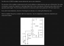
You did not use the deadtime setup of the driver ic?.
Here you can see how to setup SG ic for dead times and a schematic, the SG can drive a transfomer directly by the way. the totem poles are maybe a good idea for the big nC of irf460.
I hope you have enough info now.
succes.
I hope you have enough info now.
succes.
Attachments
hi kees52 , thanks for the quick reply and your help, but i have one question which is puzzling me . all this problems i am facing because i am using a class ab amp and have bridged it. now even the irf740 at test volume and a load of 4ohm speaker . the bridged ab amp has 4 transistors per channel and the power i feed to it from the smps is +/-52volts.
today when i used the irf740fets, the smps at idle does not heat , but at powering the amp with 4ohms woofer for five seconds . the irf 740fets(although they are mounted on a heatsink) heated up and de natured and failed. the same case happened at irfp460(but they lasted longer)
why is it that i have ever used class d amp circuits +/-49volts with a 4 channel class d and 2channels are bridged driving hard a 4ohm woofer, and other two channels driving 6ohms mid each individually. but the smps similar to this one ,but never heated to this extremes like when using this ab amp. also the smps never failed when driving the classd amps . unlike now it is over heating and fets failing driving only 2channels bridged class ab amp ??
Hi
Most of the time when do load a smps and the deadtimes are wrong you can get this problem.
An amp is not the good load for test because it is quite changing with music.
test resistors are much better or a lamp(s) for coninu load until the max.
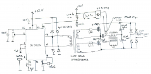
You have mede a transformer for driving the mosfets, and use extra transistors after the smps ic SG but this chip has already beefy drivers in it, and can drive transformer in one go, maby the old BD transistors are not that fast in rise/falltmes.
Have you checked the Vgs waveforms on a scope to ensure you're getting clean abrupt switching of the FETs?
How much is the primary current?
Most of the time when do load a smps and the deadtimes are wrong you can get this problem.
An amp is not the good load for test because it is quite changing with music.
test resistors are much better or a lamp(s) for coninu load until the max.
You have mede a transformer for driving the mosfets, and use extra transistors after the smps ic SG but this chip has already beefy drivers in it, and can drive transformer in one go, maby the old BD transistors are not that fast in rise/falltmes.
Have you checked the Vgs waveforms on a scope to ensure you're getting clean abrupt switching of the FETs?
How much is the primary current?
hi kees2. my startup is a small travel charger about 500ma 12vlts for startup. then after the smps has started it uses its own auxillary supply of abt 14volts but i have used regulator 7812 so the whole circuit plus the gdt receives 12volts.
currently i dont have a scope and i only use a digital multi meter.
currently i dont have a scope and i only use a digital multi meter.
hi all and thanks for the reply , i think it is because i use 7812 regulator even before the gdt , and maybe the home wound gdt requires more current than the 7812 can provide . also not using bd139/140 as buffer transistors and using a1020 and c2655 as buffers for the gdt
Maybe a low drop regulator?
then it starts better, but you wrote it get warm when have load, do you have a resistor for cold start? before the transformer widning takes over?
If the supply runs, then I think it is not the regulator but the driving of the mosfets, a pulsshaper is maybe the answer because when using a puls transformer
it is quite a good update.
http://ferroxcube.home.pl/news/gate drive trafo.pdf
it is quite sensitive for good design, of not the pulses are distorted, slowed and deadtimes affected.
Last edited:
hello all , i have an issue the smps ...
Your high power output rectifiers are loading the same phase...
or to put it another way:
your output high power looks to be designed for a flyback circuit.
while your input side is push pull.
Yes, No ?
Attachments

More than this gate-transformers are problematic in case of varying duty-cycles. And yes, this looks like some pwm controlled hard switching half bridge converter. Without secondary inductors prone to burn on first overload. Reminds me of these wretched converters that often fail in car audio amps.
thanks all for the reply. so should i use full rectification at output ,i.e using full wave ( four diodes instead of just using one diode) ?
Also should i remove the 7812 reulator in the drive board for smps side?
And where should i place the inductors? kindly help with a rough schematic.
Also should i remove the 7812 reulator in the drive board for smps side?
And where should i place the inductors? kindly help with a rough schematic.
Your high power output rectifiers are loading the same phase...
or to put it another way:
your output high power looks to be designed for a flyback circuit.
while your input side is push pull.
Yes, No ?
thanks bucks and dug for the reply. kindy dug please provide a simple schematic for an effecient output diode rectification . because i am using halfbridge smps.
A halfbridge is still a push-pull to the transformer.
Take one of your 8T power windings and switch the two wires.
Then loading will be on both phases.
There are other ways but if you have built it already then that way is an easy try.
Take one of your 8T power windings and switch the two wires.
Then loading will be on both phases.
There are other ways but if you have built it already then that way is an easy try.
thanks dug for the reply, but just wondering , how comes other loads the smps does not overheat? only at full bridge class ab of +/-60vlts when loaded with a 4ohms woofer.
any ways i will try and give you feedback.
any ways i will try and give you feedback.
thanks dug for the reply, but just wondering , how comes other loads the smps does not overheat? only at full bridge class ab of +/-60vlts when loaded with a 4ohms woofer.
any ways i will try and give you feedback.
any ways i will try and give you feedback.
😎hi all more half bridge boards version for higher power handling .they have more banks in capacitor boards are hp 20cm x 15cm and mp 20cm x 10cm
ideas and suggestions are highly welcomed .have fun and post your builds😉
hello all , this smps still puzzles me , i made it about five years ago , it did behave the same as my current issue.
at +/-55volts it supported classd in bridged mode with a 3.2 ohm speaker and it had no issue at all with heating . and it only warmed and just put a small sink.
at +/-55volts using a class ab it failed after sometime.
just wondering has anyone used high power class ab with smps with success??? 😕😕😱
Class ab does take less current? maybe the class D did draw some more, special with a strict deadtime.
Some of these smps do not like open outputs, and as a class ab just draw 100/250 mA when there is no sound it can be the cause. There is a pin for this kind of low draw so smps stays stable.
Is your smps a resonance or a hard switch version? I recommend for audio always a resonance type, these have very much less EMI.
Try a dummyload and see if it does go faulthy or heating.
failure - Why can a switched-mode-power-supply be dammaged without load? - Electrical Engineering Stack Exchange
regards
Offline full-bridge SMPS....need helpthanks bucks and dug for the reply. kindy dug please provide a simple schematic for an effecient output diode rectification . because i am using halfbridge smps.
In case of a hard-switching, pwm-controlled converter this is the standard option.
Instead of calling for a simple schematics:
Did you check your design with LTSpice?
Can you tell what kind of bridge smps this is, i.e. hard switching or soft-switching?
In case of hard-switching, which range of duty-cycle does your pwm run through?
Are you aware of extra component stress due to hard-switching?
Do you know about the problems transferring varying duty-cycles through a gate-transformer?
How do you protect you primary MOSFETs from power-up overload caused by secondary inrush-current of empty bulk caps?
Can you measure primary voltages with a scope?
Can you measure primary currents?
If this is too complicated for you I recommend strongly to stop any tinkering with smps in the kW-range until you grasped at least the basics.
And if you believe a "simple circuit diagramm" will solve all your problems then you are at the beginning of a steep learning curve.
Btw for my knowledge discussions about lethal smps projects are not welcomed here.
Last edited:
- Home
- Amplifiers
- Power Supplies
- Offline full-bridge SMPS… need help