It would be easier to help with problem if you would provide schematic of your design
along with transformer contruction details,Your winding of transformer might be wrong.
along with transformer contruction details,Your winding of transformer might be wrong.
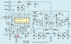
car smps
i creat this one
when i conect battry cable the red led turn on
the mosfets is hote and exit voltage is +-5vdc
i use 4 irfz44n mosfets
can you creat this one?
thanks
how about this shematic?It would be easier to help with problem if you would provide schematic of your design
along with transformer contruction details,Your winding of transformer might be wrong.
i creat this one
when i conect battry cable the red led turn on
the mosfets is hote and exit voltage is +-5vdc
i use 4 irfz44n mosfets
can you creat this one?
thanks
Attachments
I will look into it,I think I see the problem
Hi
In my country the oclock is 1:55am
Can i resive 15 amper or 20?
Can i use more irfz44 and etd39 for more power?
Where is the problem?
Transformer
I suspect your transformer is your problem; check this site for proper design
and construction.
New Page 1
I suspect your transformer is your problem; check this site for proper design
and construction.
New Page 1
car smps
where is my shematic wrong?why red led is turn on?when i dont conect the core that is turn on( red led)
I suspect your transformer is your problem; check this site for proper design
and construction.
New Page 1
where is my shematic wrong?why red led is turn on?when i dont conect the core that is turn on( red led)
The red led is connected to feedback(output of error amp) and will turn on red led when you apply power because of the way it is connected,look at P1,R13 connection and R14.I think if you adjust P1 you will get the red led to turn off(has nothing to do with why your supply does not work.Visit the website I provided and all will be explained ,Start with the correct core for the power requirements and wind it according to instructions,test the inductance with a VOM that has an inductance feature,fed a signal into the primary and check secondary signals.Refer to info at ESP website on checking transformers before mounting.Whatever control IC you use you should read the datasheet,check block diagram of internal circuit to understand its functions.Don't copy a design unless it has been proven to work and a proper PCB is supplied but if want to learn design in stages and check each one, start with control IC first(only requires a few components to function and you can do this on a bread board)apply feedback and check outputs to see the PWM signal and make sure it provides the correct outputs.Once you have the control part working the rest is cut and try to obtain the power you need(use dummy loads)only connect amp when all is well.
Last edited:
By the way mouse over (New Page 1) that will take you to a website that should clear up
a few of your questions...
a few of your questions...
Thanks for your reply
You doin best for me and i say very thanks to you my friend.
I see your web site
That smps work with sg3524
I try to find some think in my smps site but the site languich is turkish and main pdf file is rushen maybe.
I dont know this languich.
I try to find smps with tl494 because i have meny of them.
In main site of may smps they use irfz44 and etd 39.
I try to confige red led with pot1 but it was not work.
Can you advice to me one shematice of this topic?
Thanks my dear friend
Have a nise day
Get the datasheet for tl494 and take a good look,the difference between the pins you need to use and the SG series in very little,google for an atx power supply schematic it might help as most of them use the TL494.
Here is another circuit that uses the tl494 and it powers a amplifier:
DC to DC Converter 12V to ± 38V car amplifier power supply ? Power Supply Circuits
DC to DC Converter 12V to ± 38V car amplifier power supply ? Power Supply Circuits
thanks for your helping
Thanks friend
I see that befor
That is avery big treat
Are you have a corect shematic in this site that can be ofer to me?
Thanks friend
I see that befor
That is avery big treat
Are you have a corect shematic in this site that can be ofer to me?
thanks
You are a good man
Thanks
I will see and say what i findout from this site
Thanks
Here is another circuit that uses the tl494 and it powers a amplifier:
DC to DC Converter 12V to ± 38V car amplifier power supply ? Power Supply Circuits
You are a good man
Thanks
I will see and say what i findout from this site
Thanks
3m,I purchased 3 rolls 2 in. wide(yellow) @35.00ea. other than that black electrical tape will do the trick.
Last edited:
I searched for high temperature tape for myself about a month ago. This was the best deal i found. But i did not buy any yet. I was also thinking of using plain clear packing tape. It is $1 a roll 2“ wide and made of mylar.
http://www.1stmaskingtape.com/Blue_polyester_masking_tape.php
Blue Masking Tape can withstand temperature up to 400°F/204°C. It is packaged in a 3" core and is 72 yards long.
1/2" wide x 72 yards $5
Green masking tape is made of 2 mil thick polyester and 1.5 mil thick silicone adhesive. It can withstand temperature
up to 400°F/204°C. It is packaged in a 3" core and is 36 yards long. This is our most popular powder tape.
1/2" wide x 36 yards $3
Red masking tape is made of 1 mil thick polyester material and 3 mil thick silicone adhesive. It can withstand
temperature up to 400°F/204°C. It is packaged in a 3" core and is 36 yards long
1/2" wide x 72 yards $8
P.S. Mylar is a high temperature plastic.
Last edited:
There are many tapes that can be used, I just use the 3m brand and you can also use double or triple insulated AWG or Litz wire with outer cover.By the way 4mm thickness a layer eats up a lot of bobbin area,less room for wire,windings are futher from each other could add to leakage inductance and capacitance.
Last edited:
- Home
- Amplifiers
- Power Supplies
- Offline full-bridge SMPS… need help