I can't remeber what was the performance of Stewin's PSU, but as for the core he used I presume it is above 70W, which means here in the EU the PFC would be mandatory for that PSU. I don't know the regulations in the US though but PFC is always recommended so IMHO it always worths the hassle.
As for the 110V, if you're lazy you can simply half the number of primary turns and adjust the frequency if necessary (and mind the core and FET temperatures!). Although I would strongly suggest using a transformer calculator to find the correct values.
Is using PFC mandated by EU law for every one-off DIY project that uses over 70 Watts?!!
I don't think soIs using PFC mandated by EU law for every one-off DIY project that uses over 70 Watts?!!
I don't think so
Thank you. I hope not. That would be outrageous and disappointing.
check posts #1157,A solution that might fit your needs
Thanks Chas, I will read the paper and try to do some calculations.
@gootee
No, that is a restriction for marketing them. You can build whatever you want I only mentioned it as a comparison as the other member was not sure whether to put a PFC to it or not. But yeah I forgot to mention my comparison does not touch upon DIY stuff.
No, that is a restriction for marketing them. You can build whatever you want I only mentioned it as a comparison as the other member was not sure whether to put a PFC to it or not. But yeah I forgot to mention my comparison does not touch upon DIY stuff.
Can I use the FR302 diodes in place of the MUR120 ? I can't find them around here... I think of placing 2 of the FR302 for each MUR120, will it work? Mi goal is +/-70 Vdc @ 300 watts with an old atx EE core (area=0.97 cms2)
I'll try some other distributors to see if they have this mur diodes...
Thanks.
Luigi
I'll try some other distributors to see if they have this mur diodes...
Thanks.
Luigi
where do you want to have FR302's? output diodes?Can I use the FR302 diodes in place of the MUR120 ? I can't find them around here... I think of placing 2 of the FR302 for each MUR120, will it work? Mi goal is +/-70 Vdc @ 300 watts with an old atx EE core (area=0.97 cms2)
I'll try some other distributors to see if they have this mur diodes...
Thanks.
Luigi
where do you want to have FR302's? output diodes?
Yes, output diodes. As of today, i haven't found the mur120 diodes 🙁
In the output i'll have +/-70 volts @ 3 amps, i think with 2 fr302 diodes in parallel in place of each of the output diodes (8 diodes in total) i'll have enough. Bad idea? I'll keep looking for the mur diodes, maybe i'll have better luck. Some specs for the fr diodes:
http://www.rectron.com/data_sheets/fr301-307.pdf
FAST RECOVERY RECTIFIER
VOLTAGE RANGE 50 to 1000 Volts CURRENT 3.0 Amperes
Thanks
Luigi
it could work, they are not the best, but far from bad...
you could look at any other MUR device, if any you can get
like mur1520-1560...
you'll just have to try, small load, and increase it... and check how waveforms are and if diodes don't get too hot
you could look at any other MUR device, if any you can get
like mur1520-1560...
you'll just have to try, small load, and increase it... and check how waveforms are and if diodes don't get too hot
The diode recovery time of 150ns??/...normal for smps 30 - 60ns depending on design,I suggest you check datasheet and design requirements, also core seems small for amount of wire needed to wind transformer and get good results. A 50Khz fsw will require about 38turns in primary and about 24turns for secondary plus aux supply of 4 turns,AWG #20 in both or multiple strands of smaller wire...Save time and money and review design and have all your parts before starting.I am in the Dominican Republic and can send you Diodes,transformer cores and bobbins as well as other parts if you will pay my costs , plus shipping, the only core sets I have at present are ETD49.
I am in the Dominican Republic and can send you Diodes,transformer cores and bobbins as well as other parts if you will pay my costs , plus shipping, the only core sets I have at present are ETD49.
Thank you chas1 for the kind offer 🙂 , I found the mur1520 diodes in a local distributor (didn't buy them, just found them) , and for the cores, I'll try with what i have around (atx pc power supply) to keep costs down. If this don't work out as good as i want, i'll try to get a bigger core. Someone knows where to buy etd cores online that ships to USA? I can have someone to bring them to Colombia.
I'll begin to calculate the wire turns for this little core, i'll keep posting.
Thanks
Luigi
For core sets ebay will be your cheapest bet, you should be able to find the ETD44 with bobbins and clamps for about 6 to 10 dollars,the shipping will costs more than the core set and bobbin.Good luck with your project...
Attachments
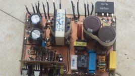
Stewin
That is some outstanding work. I am happy to see you complete your project. Your work makes me want to finish what I started a long time ago.
Given what you have to work with and more, you have done a super job. Keep up the Great work.
Please show us later the whole project when it done.
Thanks for Sharing😉
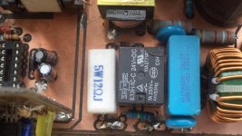
For long term use , I would check the components in the startup circuit,I think you can do without the voltage regulator.The 24volt supply would be about 14 volts according to the components used.The 2.2k resistors are rated at two watts when a pluse exceeding 10 watts will be present during startup and if the 150k is 1/4 watt two resistors should be used to obtain its value because the voltage breakdown will be exceeded in a single unit.
thanks krisfr
i used zeener diodes as voltage reg because the voltage adjust never worked i set the voltage to +/-36volts pls see more photos at the diy smps link
😉
http://www.diysmps.com/forums/showthread.php?250-IR2153-smps-with-short-circuit-protection./page21
Forced Gifting
+/- 80volt outputs but output caps (4700uF@50VDC)?/
i used zeener diodes as voltage reg because the voltage adjust never worked i set the voltage to +/-36volts pls see more photos at the diy smps link
😉
http://www.diysmps.com/forums/showthread.php?250-IR2153-smps-with-short-circuit-protection./page21
Forced Gifting
Last edited:
I don't belong to diysmps,as for your voltage adjust and other sections of your design use sources you can find on the web or simulate the circuits in question until you get them to behave and try to stay away from power grabbers like zener regulators that require more passive components(heat generators).A good free simulator is LTspice and its free the learning curve is short and has a excellent forum.I will post a simulation of your design shortly.Check your design before PCB layout, I would make the first one slightly larger to make it easier to find problems and allow room for modifications,I would layout a farm of pads along one side or a corner for design changes of circuits for prototype..small signal stuff.
Last edited:
- Home
- Amplifiers
- Power Supplies
- Offline full-bridge SMPS… need help