I used trafos from Block, bought from rs-online. I use a 400VA from Block in my F6. Nicely made and works fine in the F6. I was going to get 200 or 250VA but the 300VAs where less expensive than the 250VA.
I also mounted the caps on a piece of wood for easy change if I have problems with the surplus caps and have to install smaller caps and pcbs.
If everything works fine I will bolt the cap brackets directly to the bottom plate .... If Im not to busy listening to music of course 🙂
I also mounted the caps on a piece of wood for easy change if I have problems with the surplus caps and have to install smaller caps and pcbs.
If everything works fine I will bolt the cap brackets directly to the bottom plate .... If Im not to busy listening to music of course 🙂
Sounds about right, i only managed to finish the last few details of my F6 after about a year in operation 😀
Side question for the knowledgeable:
I was looking at the 6moons review of the production M2, and noticed a few things in the interior shots they posted that i got to wondering about:
- Considering several examples of the PT coupling to the edcors, i wonder why Mr. Pass chose not to place the PT further towards the front of the chassis. Also, is there a reason he is placing the diode bridges as far from the CRC board as possible, rather than between PT and CRC?
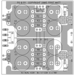
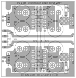
- It looks like the CRC board in many of the FW amps has a track for running 115/230V AC in the center of the board, with the PT primaries connected on the other side and space for thermistors. Also there are V+/-/gnd taps on either side of the board. It seems like a neat solution. I suppose one could do something similar with AC simply running the AC from the inlet between the caps (or under the base plate a la ZM), but has anyone implemented these features in a DIY-available CRC board?
(this is the photo im talking about btw:
http://www.6moons.com/audioreviews/firstwatt11/open1.jpg)
Side question for the knowledgeable:
I was looking at the 6moons review of the production M2, and noticed a few things in the interior shots they posted that i got to wondering about:
- Considering several examples of the PT coupling to the edcors, i wonder why Mr. Pass chose not to place the PT further towards the front of the chassis. Also, is there a reason he is placing the diode bridges as far from the CRC board as possible, rather than between PT and CRC?
- It looks like the CRC board in many of the FW amps has a track for running 115/230V AC in the center of the board, with the PT primaries connected on the other side and space for thermistors. Also there are V+/-/gnd taps on either side of the board. It seems like a neat solution. I suppose one could do something similar with AC simply running the AC from the inlet between the caps (or under the base plate a la ZM), but has anyone implemented these features in a DIY-available CRC board?
(this is the photo im talking about btw:
http://www.6moons.com/audioreviews/firstwatt11/open1.jpg)
don't do just everything as Papa is doing

Just because? 😉
Mark, thanks that is what I was expecting. One of the reasons I asked was actually that I thought (based admittedly on total ignorance!) hanving ac so close to your dc source would be a bad idea.
What about the placement of the rectifiers? Is that just aesthetic?
Last edited:
Papa is having all those holes in bottom pre-drilled in case fab.
most certainly he's not finding anything critical, so why change it
most certainly he's not finding anything critical, so why change it
M2 Headphone Amp
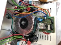
M2 headphone build. After getting very impressed with the the performance of the M2 amp I decided to build a headphone amp too. Used an oversized 300va transformer with separate windings for the left and right channels. Added voltage regulators too. Biased current was set at 300mA with +/- 22V rails.
M2 headphone build. After getting very impressed with the the performance of the M2 amp I decided to build a headphone amp too. Used an oversized 300va transformer with separate windings for the left and right channels. Added voltage regulators too. Biased current was set at 300mA with +/- 22V rails.
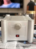
M2 Headpone Pictures
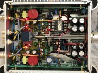
The chassis has two compartments. The lower houses the transformer, bridge rectifiers, soft start modules and first filter capacitors. The upper compartment houses the amp boards, regulators, post regulators filter capacitors and headphone protection module.
The chassis has two compartments. The lower houses the transformer, bridge rectifiers, soft start modules and first filter capacitors. The upper compartment houses the amp boards, regulators, post regulators filter capacitors and headphone protection module.
Attachments

I have built a Teabag M2. Recently, I had to replace the fuses twice, 2 incidents happened i turned off the amp to reconnect some wires. The amp is still working fine, is there anything I can check to find the root cause of the blown fuses?
mains NTC wasn't cooled off ?
say that 3-4 min are necessary
and , it really depends how big Iron is , and how much cojones in C bank ....... and what value of fuse is in
so , besides problem , you didn't said much more
say that 3-4 min are necessary
and , it really depends how big Iron is , and how much cojones in C bank ....... and what value of fuse is in
so , besides problem , you didn't said much more
I use 4x22kuF per rail and the 1.25A slow blow fuses as recommended by Papa. The heatsink is the Deluxe 4U.
For my F5T, i never had this problem switching on and off without popping the fuses.
For my F5T, i never had this problem switching on and off without popping the fuses.
and donut is ?
how much VA ?
with 1A25 , you're good up to 300VA , considering 220-240Vac mains
how much VA ?
with 1A25 , you're good up to 300VA , considering 220-240Vac mains
Transformer VA? I now use a t1.6 for my f6 with 400VA and haven’t had the issue for a while, though I also took it to reflect insufficient cooling of the itc as ZM mentioned.
Donut is 400VA.
So I need to up to T2A?
So I need to up to T2A?
400VA ?
say that T2A is more appropriate (220-240Vac mains)
- Home
- Amplifiers
- Pass Labs
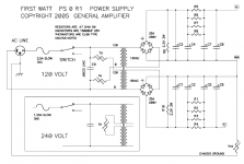
- Official M2 schematic