Did yours blow the 1A25 fuses?Transformer VA? I now use a t1.6 for my f6 with 400VA and haven’t had the issue for a while, though I also took it to reflect insufficient cooling of the itc as ZM mentioned.
If you have trouble with this, bypass the thermistor with a heavy duty relay controlled by a timer circuit that closes the relay 1-2 minutes after power is applied. Then the thermistor can cool & be ready if you have to turn the amp off & back on.mains NTC wasn't cooled off ?
say that 3-4 min are necessary
and , it really depends how big Iron is , and how much cojones in C bank ....... and what value of fuse is in
so , besides problem , you didn't said much more

Does anyone have a digikey or mouser BOM they can share?
I have tea bag's boards, edcors, and input and output transistors but need all the other parts still.
I have tea bag's boards, edcors, and input and output transistors but need all the other parts still.
Ah I must have missed that. Gracias! Just what I needed.
Question regarding that document:
C2 Bypass and C3 Bypass are marked 'opt'. Is that really optional? When would one use it and when not?
Same with R6, R7
.
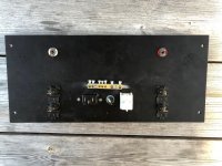
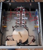
My M2 with Harris/Vishay mosfets have been a great enjoyment but I thought that it needed bigger heat sinks especially in summertime. So I put together a new M2. I tried to make it as best I can according to standard scheme. It got bigger heat sinks, “unobtainium” fets and some overkill(!) resistors. I really think Harris/Vishay and linear systems j-fets works fine! This time I hade the opportunity to explore other components. My M2 case is not an imaginary one, not worthy the f-word. I kept a scandinavian clean design. Now I can’t stop listening. I like it a lot! Listening level is normally from 30-60 dB in the sofa in a big room. The difference? Eh, hard but if I was forced. They are both detailed and pleasant. My old was more vibrant and this one more coherent/smooth. I can't say if it's the fets or other stuff.
B1 as pre. I know, buffer-buffer but sounds so good.
Transformer: 400VA
PSU capacitors: PEH200 15kuF
PCB: Tea-Bags M2 Clone
Mosfet Iq: 1.45A with 0R47
Heat sinks: 4u 400, 2x0,39 C°/W
J-fets: 2SK170/2SJ74
Mosfet 2SK1530/SJ201
According to NP temperature scale 🙂 bloody hot with ambient of 29-30 degrees C, bloody hot summer, but still 24 degrees above ambient.
Changes from official schematic:
R8,R9: 120ohm (didn’t have 100’s)
Added 1k to R7 reach zero offset.
Bypasses due to Tea-Bags pcb.
Two blue leds show a dim light under front in dark room.
Speakers 100+dB
I took a chance with transformer ground using the power cable. Seams to be working.
I have a tiny buzz of ~100/150Hz only noticeable in dead quiet room and an ear close to the speaker. Perhaps mu-metal would do something(?)
Any thoughts are welcome.
I am grateful for this hobby that Torb introduced and I send big thankyous to NP, ZM, Tea-bag and Torb.
Attachments

ok , Fugly!
🙂
one thing - I had impression , when using mains filters in whatever size , it was having somewhat bad influence on amp's dynamics
can't tell for sure , but worth investigation - listen for few weeks , then try without filter in circuit ...... and leave what's better

🙂
one thing - I had impression , when using mains filters in whatever size , it was having somewhat bad influence on amp's dynamics
can't tell for sure , but worth investigation - listen for few weeks , then try without filter in circuit ...... and leave what's better
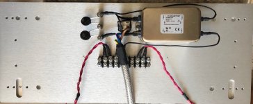
That’s a handsome looking amp. Out of curiosity, do you do anything else than tightening the cap screw terminals to fix the psu wires in place? What gauge are those solid core wires?
Nice! To improve the dynamics and frequency extremes' extension:
1. (at least) Double the wire thickness: bridge rectifiers - capacitors bank - Vcc/Vee PCB eyelets. Try to use solid core copper wire.
2. Remove the mains' filter
1. (at least) Double the wire thickness: bridge rectifiers - capacitors bank - Vcc/Vee PCB eyelets. Try to use solid core copper wire.
2. Remove the mains' filter
I would use a copper clad PC board material to connect all those capacitors, resistors for the PS. Maybe ad some foil caps next to those large caps.. Just an advise.
Question regarding that document:
C2 Bypass and C3 Bypass are marked 'opt'. Is that really optional? When would one use it and when not?
Same with R6, R7
.
Probably need to read the materials, answers are there.
The optional resistors are optional values in case the offset isnt fully able to null to zero, The caps, well some use the 10uf Silimic along with a bypass, then others use a film cap in place of the whole shebang....Some cap will have to be there
diyAudio - Tea-Bag
scroll down to the M2 info, you will see about caps.
The resistors may need adjusted if you cant zero the offset. Some value of resistor needs to be there. I found Tea's choices worked as planned.
As somewhat of an uninitiated myself, I find it helpful to read entire threads on particular amp I am building, taking notes on certain intricacies and ignoring some of the chatter. Then ask questions like you are. Then when clear in head with project, commence assembly.... Stopping and asking anytime question arises.
Teas boards are heavy and solid. Very nice until mistake is made and something needs unsoldered. like the resistors you asked about...you will see folks leaving long leeds until they have zero offset. Then permanent solder.
Russellc
Last edited:
Thank You all for your thoughts!
ZM, You are too kind.
I will try without filter in a week or two.
Solid copper wire 16G for PSU tightened with spring washers. A copper clad is a good idea!
Solid copper for ground and speakers and stranded Alpha wire 16G to power M2. Any ideas how to use thicker cables when pcb has 16G as limit?
ZM, You are too kind.
I will try without filter in a week or two.
Solid copper wire 16G for PSU tightened with spring washers. A copper clad is a good idea!
Solid copper for ground and speakers and stranded Alpha wire 16G to power M2. Any ideas how to use thicker cables when pcb has 16G as limit?
ok , Fugly!
🙂
That’s a handsome looking amp. Out of curiosity, do you do anything else than tightening the cap screw terminals to fix the psu wires in place? What gauge are those solid core wires?
Nice! To improve the dynamics and frequency extremes'[...]
I would use a copper clad PC board material to connect all those capacitors, resistors for the PS. Maybe ad some foil caps next to those large caps.. Just an advise.
Last edited:
Probably need to read the materials, answers are there.
The optional resistors are optional values in case the offset isnt fully able to null to zero, The caps, well some use the 10uf Silimic along with a bypass, then others use a film cap in place of the whole shebang....Some cap will have to be there
diyAudio - Tea-Bag
scroll down to the M2 info, you will see about caps.
Thanks for that. I somehow missed it.
Thanks for the advice. Yeah, it's a lot of work to read entire threads and I'm usually sidetracked before I'm halfway through. 😱The resistors may need adjusted if you cant zero the offset. Some value of resistor needs to be there. I found Tea's choices worked as planned.
As somewhat of an uninitiated myself, I find it helpful to read entire threads on particular amp I am building, taking notes on certain intricacies and ignoring some of the chatter. Then ask questions like you are. Then when clear in head with project, commence assembly.... Stopping and asking anytime question arises.
Building the amp is the easy part. 😀
.
I would use a copper clad PC board material to connect all those capacitors, resistors for the PS. Maybe ad some foil caps next to those large caps.. Just an advise.
Do You mean CCA copper, copper over aluminum, or solid copper?
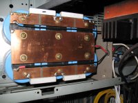
I meant something like these, please take a look at the picture.
In case if is not good enough you can use solid copper- I think this one is the best and cheapest solution, also you can use one piece by cutting out the copper traces.
I prefer this solution "double-sided copper clad board" with thick copper foil and brass washers and brass screws.
You can use wire connectors and you do not need to worry about how to connect a thicker wire.🙂🙂
Attachments
Hi gaborbela. Where do you get the board with thick copper plating on both sides, and for that matter brass screws and washers?.
I meant something like these, please take a look at the picture.
In case if is not good enough you can use solid copper- I think this one is the best and cheapest solution, also you can use one piece by cutting out the copper traces.
I prefer this solution "double-sided copper clad board" with thick copper foil and brass washers and brass screws.
You can use wire connectors and you do not need to worry about how to connect a thicker wire.🙂🙂
Brass screws and washers I got from Home Depot (be careful those are standard and not metric) Cooper boards I got from the local store but you can get those from ebay also. https://www.homedepot.ca/en/home/search.html?q=Brass screws#!q=Brass screws
Thanks, Im in the metric part of the world 🙂 How thick is the copper plating? Would it not be better to use 2-4mm thick copper or aluminium plate. Im using wire (2.5mm^2 - 14awg ) now to connect 8x large 47000uF caps in my M2 build, cant be worse than thin plating ? I however really like the clean look of using copper plated board or copper plates.
Brass screws and washers I got from Home Depot (be careful those are standard and not metric) Cooper boards I got from the local store but you can get those from ebay also. https://www.homedepot.ca/en/home/search.html?q=Brass screws#!q=Brass screws
- Home
- Amplifiers
- Pass Labs
- Official M2 schematic