Pass DIY Addict
Joined 2000
Paid Member
Are the specifications defined at some unrealistic temperature differential and only accurate when the sink is way above ambient?
Yup - that one! If you take that 3U sink and push 50w of power into it, you'll see much greater than 25c rise over "normal room temperature." Some manufacturers rate the dissipation of their sinks at 80c or higher.
Subsequent quick request to 6L6...
In the spirit of making this hobby more accessible would it make sense to address this in the DIYStore with a note of explanation?
something like:
**Note heat sink performance (C/W), is typically defined at 75 or 80C. Operating heat sinks at a more reasonable 50-55C results in a lower thermal efficiency and so `standard heat sinks specs' should be reduced by ~50%
For further discussion on recommended temperatures see post http://www.diyaudio.com/forums/pass-labs/3748-aleph-186.html#post116146
I have a couple questions
First I plan to use Toshiba power mosfet I have a matched pair purchased them a few years a go, I do not see any other project to keep them in my box. I know here I would not need a matched quad mosfet.
1) Should I adjust any component value or I can use these schematics how it is? I would like to a full advantage (if there is any)at the Toshiba mosfet.
2) The 3300uF should be 35V or 25V enough? I ask because of the size of the capacitor. I will use 20-0-20 VAC transformer.
Thank you very much!
Greetings
Attachments
I have a couple questions
First I plan to use Toshiba power mosfet I have a matched pair purchased them a few years a go, I do not see any other project to keep them in my box. I know here I would not need a matched quad mosfet.
1) Should I adjust any component value or I can use these schematics how it is? I would like to a full advantage (if there is any)at the Toshiba mosfet.
2) The 3300uF should be 35V or 25V enough? I ask because of the size of the capacitor. I will use 20-0-20 VAC transformer.
Thank you very much!
Greetings
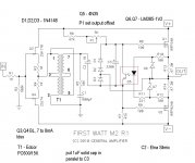
1.pretty much as is ; read notes about offset and resistor corrections
2. 16V cap is enough
flocchini
flocchini may I ask what are those gold-colored foil caps? Did you replace the 10uF electrolytic? What is the purpose I do not see input caps on the circuit? That would be a bypass capacitor on the 3300uF.
Would you be so kind to let me know, Thank you.🙂
We have a different type of PC boards with the different layout so I can not 100% understand yours.
By the way, mine is a blue color.
Thank you one more time.
Attachments
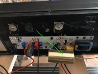
Thanks for asking.
Those caps are a replacement for the 10uF electrolytic. I will be changing them to 10uF electrolytics the next time I have my system down. Always a need to experiment.
A discussion of TeaBags boards can be found here.
M2Clone boards with 120mm UMS spacing - diyAudio
Those caps are a replacement for the 10uF electrolytic. I will be changing them to 10uF electrolytics the next time I have my system down. Always a need to experiment.
A discussion of TeaBags boards can be found here.
M2Clone boards with 120mm UMS spacing - diyAudio

I have had a good experience with 10 µF WIMA MKP10 caps at that position.🙂
Best regards, Claas
Best regards, Claas
Pass DIY Addict
Joined 2000
Paid Member
more heatsink talk
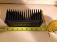
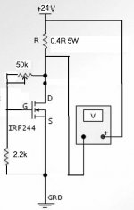
I'm building a + / - 24v 'universal First Watt' PSU in a separate chassis.
Except for the reason of heat dissipation, My amps can be rather small, at least smaller than usual.
I had in mind to use four of these smaller sinks for an M2. I was a bit worried if they would do the job... borderline maybe. I did some calculations, but didn't trust it much.
I decided to clamp an IRFP140 to it. I biased it up using a 24V supply, .4R source resistor, and a pot to adjust the bias. Running at 1.8A (0.6A excess over M2 bias for safety margin) I could only get the sink to 50c after several hours. I could top 60c with over 2A bias. This is in a 'room temperature' room.
I can be reasonably sure that these sinks are good for the application. I'm thinking that this is the best way to truly evaluate heatsinks with unknown (or even known) specs.
Attachments
........
...... I'm thinking that this is the best way to truly evaluate heatsinks with unknown (or even known) specs.
I second that
Added to the "good practice/avoid trouble" list - obvious, but I never thought of it... better than guesstimating!
Pass DIY Addict
Joined 2000
Paid Member
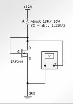
or use power resistors and xformer through variac
brain and calculator always welcome addition

brain and calculator always welcome addition
- Home
- Amplifiers
- Pass Labs
- Official M2 schematic