
I'm building a + / - 24v 'universal First Watt' PSU in a separate chassis.
Except for the reason of heat dissipation, My amps can be rather small, at least smaller than usual.
I had in mind to use four of these smaller sinks for an M2. I was a bit worried if they would do the job... borderline maybe. I did some calculations, but didn't trust it much.
I decided to clamp an IRFP140 to it. I biased it up using a 24V supply, .4R source resistor, and a pot to adjust the bias. Running at 1.8A (0.6A excess over M2 bias for safety margin) I could only get the sink to 50c after several hours. I could top 60c with over 2A bias. This is in a 'room temperature' room.
I can be reasonably sure that these sinks are good for the application. I'm thinking that this is the best way to truly evaluate heatsinks with unknown (or even known) specs.
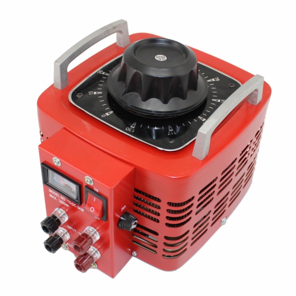
Unfortunately I don't have a brain so the calculator and variac are just looking at me waiting to do something ...

So 24V @ 1.8A = 43.2W you're pumping into one heatsink, so assuming the 2 devices are paralleled or complementary you'll be good for at least 86W dissipation right (because you're going to use 2 per side)?
For power resistor and variac, would you have to measure the voltage drop across the resistor to figure out the current going through and then measure the voltage to do the calculation? You'd need some pretty big power resistors for that correct? Would dummy loads work for that?
...
So 24V @ 1.8A = 43.2W you're pumping into one heatsink, so assuming the 2 devices are paralleled or complementary you'll be good for at least 86W dissipation right (because you're going to use 2 per side)?
...
Yup, two per side.
you'd have to subtract the heat from the source resistor...
1.8 X 1.8 X 0.4 = a whopping 1.3 watt break 🙂
But my theory is really to mimic the situation - in situation. If the M2 biases at ~1.2A as I did on the bench with a couple of parts (only the top of the OP section as an example = 24v) then I expect my sinks to hang around 40c.
The whole thing could be flawed, I haven't a brain.
Zen,
as for the "variac" (in this coontext) I suppose you are taliking about a variable load using Transistor and pot and Big resistor on heatsink ?
Regards,
Max
as for the "variac" (in this coontext) I suppose you are taliking about a variable load using Transistor and pot and Big resistor on heatsink ?
Regards,
Max
Variac is chief Mod around
variac is
variac is
An externally hosted image should be here but it was not working when we last tested it.
idss
Have someone tried comparing Jfet with idss 7mA and idss 10mA?
Which should I choose and why?
I'm using Toshiba 2SJ201/2SK1530 and schematic values.
If GR-jfet, anything to consider?
avoid source resistors for them , chill ......
and search for BL while chilling
better to drive autoformer with lower impedance , in any case
Have someone tried comparing Jfet with idss 7mA and idss 10mA?
Which should I choose and why?
I'm using Toshiba 2SJ201/2SK1530 and schematic values.
Just another datapoint. I built my M2 with 10mA jfets because that's what I had on hand. TeaBag board and corresponding standard BOM + resistor change to help bring the DC offset to zero. Sounds mighty fine to my ears and still my favorite amp. Hundreds of hours on it and zero issues.
BK
BK
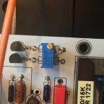
Latest hack: Bourns pot on R3/R4. Offset on Edgor back to 0mV
Interesting. Please explain how it's done.
20R0 linear Bourns pot instead of 2x 10R resistors. Leg 2 towards the Edcor.
Thanks, I can see that in the picture. I mean, how do you measure the offset on the transformer.
xformer input point red probe
gnd black probe
shoot for 0V ......... practically no more than 10mV in temp. equilibrium
gnd black probe
shoot for 0V ......... practically no more than 10mV in temp. equilibrium
Thanks ZM. That seems easy enough.
I'm waiting for my boards, etc. from Teabag and I'll do this hack.
Btw, why should one aim for 0 offset?
I'm waiting for my boards, etc. from Teabag and I'll do this hack.
Btw, why should one aim for 0 offset?
When I measure the DC resistance of the Edcor primary, I get about 44 ohms. (average of two transformers)
If the DC offset voltage at the output of the 2xJFET input buffer circuit is 0.1 volts, that results in a DC current of 2.3 milliamps flowing in the primary. {Ohm's Law: I=V/R} I don't know about you but I don't want 2.3mA DC, flowing in the primary.
If the DC offset voltage at the output of the 2xJFET input buffer circuit is 0.1 volts, that results in a DC current of 2.3 milliamps flowing in the primary. {Ohm's Law: I=V/R} I don't know about you but I don't want 2.3mA DC, flowing in the primary.
Pass DIY Addict
Joined 2000
Paid Member
This is a GREAT approach. I've been thinking about doing this same thing in a few other circuits as a way to "cheat" having matched jFets. I have plenty of pairs that don't match as closely as I'd like.
- Home
- Amplifiers
- Pass Labs
- Official M2 schematic