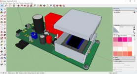
Hello, I will finish soon to mount my M2 amp from Nelson Pass with the cards that my bag bag provided on the buying group ... I ask myself the transistors output must be paired ???
cordially
cordially

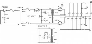
Can someone post the power supply schematics?
JP
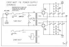
Along with Zen Mod's suggestion no one has done a powersupply pcb based on f6 powersupply.
It might be possible to have both versions on the same pcb with some sought of jumper arrangement.
F6 powersupply is different.
Has independent rc filters for each channel, also like f7 powersupply.
Has independent rc filters for each channel, also like f7 powersupply.
yup
but they're (prety much all FW PSU-s) all interchangeable .......
speaking of bipolar ones ....
but they're (prety much all FW PSU-s) all interchangeable .......
speaking of bipolar ones ....
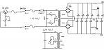
Did someone need Layout for power supply? (with CMC option)
@2 picoDumbs: attachment not readable too small
JP
@2 picoDumbs: attachment not readable too small
JP
All you have to do to have the option of mono supply or stereo supply is allow a jumper connection across the open resistor network
Attachments
Last edited:
IIRC Tea-Bag has a power supply PCB:
http://www.diyaudio.com/forums/blogs/tea-bag/923-dual-rail-power-supply-power-amplifier.html
Pico,
Can you please check and let us know?
http://www.diyaudio.com/forums/blogs/tea-bag/923-dual-rail-power-supply-power-amplifier.html
Pico,
Can you please check and let us know?
Just had a very quick glance.
To go from f6 mono to f6 stereo versions you need room for at least 2 resistors in parallel on each rail.
I don't think tea bag has included this option.
I'll look at it more closely later.
To go from f6 mono to f6 stereo versions you need room for at least 2 resistors in parallel on each rail.
I don't think tea bag has included this option.
I'll look at it more closely later.
Did someone need Layout for power supply? (with CMC option)
@2 picoDumbs: attachment not readable too small
JP
Just for reference the biggest 35V snap in caps I can find are these
ESMH350VQT683MB80T
5 pin 40mm diameter caps
If your pcb can accomodate these along with standard 2 pin snap-in caps you've pretty much catered for every possible scenario.
I think it would be preferable to have dedicated bipolar supply with better 0V connection. Possibly makes no difference, but not much of a fan of the idea of jumping to create 0V connection.
Last edited:
working on, but not my priority. Starting today, first version tomorrow, a lot to clearify before all happy...
JP
JP
If you mean matched, no.
Thank you Nelson for the answer!
B1 ∩ M2
A couple of questions on driving the M2 if someone could help please...
Back in #55 Mr Pass suggests
2/ Would it be acceptable to drive the B1 straight off the M2 PSU +24V rail, keeping the B1 PSU filtering elements R1, C1?
Thanks!
A couple of questions on driving the M2 if someone could help please...
Back in #55 Mr Pass suggests
1/ Would the B1 be a good match for driving the M2 straight into the input transformer, eliminating M2 circuit elements R1-R4 and Q3/Q4? Motivation here is mainly budget, but also I may build the M2/B1 integrated in one chassis, so why bother with the M2 JFET input stage if it would be superfluous in the application.If you have a low impedance source you can eliminate the buffer altogether.
2/ Would it be acceptable to drive the B1 straight off the M2 PSU +24V rail, keeping the B1 PSU filtering elements R1, C1?
Thanks!
FE of M2 is practically B1 (v.2 - , where v.1 was with two 2SK170)
so , that's really semantics where you are having B1 - separate or as part of M2 , as long you didn't stack in series two of them
so , make proper/regular M2 , feel free to toss selector and volume in same case
though ....... you must be sure that you're having sources with enough voltage swing
M2 having 15db of gan ......... source must have 2V5 on output , and some more for headroom
- Home
- Amplifiers
- Pass Labs
- Official M2 schematic