Work with the ones that have -24 volts on the output pin (pin 1) with the chip desoldered. So lets pick Q401 as that is in the diagram above.
Before getting heavy with it (and particularly as three of the four opamps all have weird voltages) you should check the grounds. Make sure that R409 (is it 409, the 150 ohm) is grounded. If that is floating then all sorts of things will happen.
Before getting heavy with it (and particularly as three of the four opamps all have weird voltages) you should check the grounds. Make sure that R409 (is it 409, the 150 ohm) is grounded. If that is floating then all sorts of things will happen.
You need to see why pin 1 has this -24 volts on it even when resoldered. Something very fundamental is wrong here for three of the four opamps to behave like this.
It might be quickest to desolder one and double check the voltages on the pads. Pads 1 and pin 7 although linked by the feedback network are both AC coupled via C405 and C417 and so there should be zero volts DC on both pins with it unsoldered.
If not then remove the caps and check again. There has to be zero volts now.
Also check first that you have not got -25 volts on the other end of C417. If there is then that would cause the cap to breakdown and put that voltage on the chip.
Those look perfect results.
I'm going to suggest you remove the one known good working chip and fit it in the location you have just measured those perfect voltages. The voltage on pin 6 (non inverting input) defines the basic DC input conditions and you did actually have 0 volts there even with the chip fitted. So that's good. Pin 7 is the inverting input and is DC coupled back to the output pin giving 100% DC feedback, in other words pin 7 should follow pin 6 and you should see zero volts output.
I'm going to suggest you remove the one known good working chip and fit it in the location you have just measured those perfect voltages. The voltage on pin 6 (non inverting input) defines the basic DC input conditions and you did actually have 0 volts there even with the chip fitted. So that's good. Pin 7 is the inverting input and is DC coupled back to the output pin giving 100% DC feedback, in other words pin 7 should follow pin 6 and you should see zero volts output.
Check the voltage on the other end of C417. It should be zero.Q401
Remove C405 and C417 if needed to see where the voltage is getting in.7 -700MV
I going to test these op amps on the breadboard tomorrow so I can be sure they are OK. I De soldered half the board and found bits of print falling off, so I'm going to have to check it all. I have partial sound on one channel now so I am making a bit of progress
is there a way to test an opamp out of the board?
You can do basic tests by building it up into a simple circuit.
You only need 1 resistor provided the opamp is 'unity gain stable' although you will probably have to shove a small cap between pins 3 and 5 to keep it stable.
What was the type number of them again?
That's one of the old Hitachi opamps, highly regarded back in the day. It should be easy to test on a breadboard. Just make it up into a standard gain block using say 10k and 100k resistors. Add the cap for stability and take it from there.
These are standard configurations.

These are standard configurations.
so all the op amps appear to be ok witha basic test.
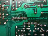
The board is a mess from who ever worked on it before, print lifted all sorts, so i cant realy trust what im testing, so ive decided to remove the board completely and rebuild it from scratch.Im going to be keeping this amp for myself so the additional work wont go to waste, at least then ill know its all good, and it will be easier to do out of the amp
The board is a mess from who ever worked on it before, print lifted all sorts, so i cant realy trust what im testing, so ive decided to remove the board completely and rebuild it from scratch.Im going to be keeping this amp for myself so the additional work wont go to waste, at least then ill know its all good, and it will be easier to do out of the amp
Sounds like a plan. Opamps are generally super reliable. Connecting supplies with wrong polarity is about the only thing that will damage them in a circuit like this.
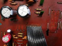
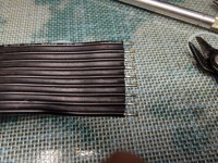
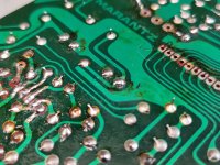
Notice how the tape connections look like they would be connected. Now look at the board, furthest right. So I removed and stripped back ready to connect back. Right in the middle centre, the cap is away from the print
Attachments
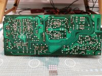
so a bit of progress-board back in
not perfect but better than it was with Q401 and 2
Q401
1 40mv
3 1mv
4 -23v
5 -16v
6 -60mv
7 1mv
8 +23v
Q402
1 40mv
3 -50mv
4 -23mv
5 0mv
6 1mv
7 0mv
8 +23v
but
QE01
1 -14V
3 +23V
4 -23V
5 -23V
6 1MV
7 -17V
8 +23V
QE02
1 -23V
3 when i touch this with the meter it trips the breaker(it did this before)
4 -23v
5 -23v
6 5mv
7 -23mv
8 +23v
- Home
- Amplifiers
- Solid State
- Odd things going on with a Marantz PM500